Nissan Altima (L32) 2007-2012 Service Manual: Function diagnosis
LUBRICATION SYSTEM
Lubrication Circuit
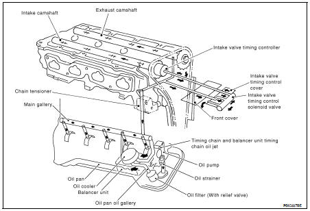
Schematic
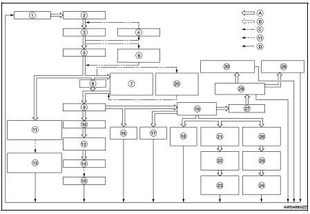
1. Oil pan
2. Oil strainer
3. Oil pump
4. Regulator valve
5. Oil filter
6. Relief valve (Built in oil filter)
7. Oil cooler
8. Bypass
9. Main gallery
10. Main bearing
11. Timing chain and balancer unit timing
chain oil jet
12. Connecting rod bearing
13. Timing chain and balancer unit timing
chain
14. Connecting rod
15. Piston
16. Balancer unit
17. Chain tensioner
18. Camshaft bracket (No.1)
19. Cylinder head oil gallery
20. Relief valve
21. Intake camshaft bracket (No.2)
22. Intake camshaft oil passage
23. Intake camshaft journal
24. Exhaust camshaft journal
25. Exhaust camshaft oil passage
26. Exhaust camshaft bracket (No.2)
27. Front cover
28. Intake valve timing control cover
29. Intake valve timing controller
30. Intake valve timing control solenoid
valve
A. Oil passage
B. Return oil passage
C. Bypass
D. To oil pan
Special Service Tool
The actual shape of the Kent-Moore tools may differ from those tools
illustrated here.
Commercial Service Tool
...
 Preparation
 On-vehicle maintenance