Nissan Altima (L32) 2007-2012 Service Manual: Ground
Ground Distribution
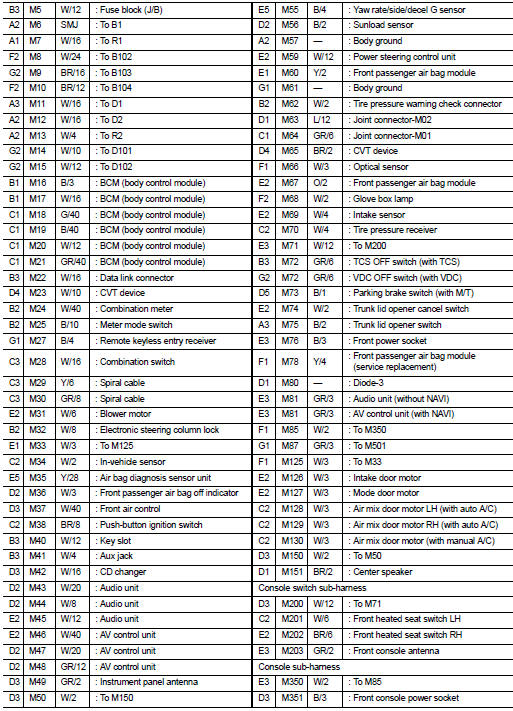
MAIN HARNESS
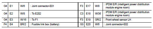
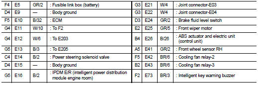
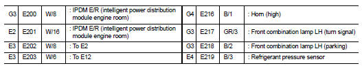
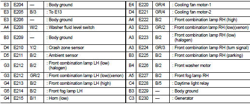
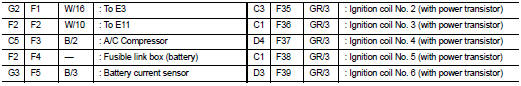
ENGINE ROOM HARNESS
FRONT END MODULE HARNESS
ENGINE CONTROL HARNESS
BODY HARNESS
BODY NO. 2 HARNESS
HARNESS
Harness Layout
HOW TO READ HARNESS LAYOUT
The following Harness Layouts use a map style grid to help locate connectors on the drawings: • Main Harness, Console Sub-harness and Console Switch Subharness
• Engine Room Harness
• Engine Room Harness (Passenger Compartment)
• Front End Module Harness
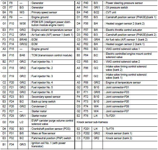
• Engine Control Harness (VQ35DE) and Knock Sensor Sub-harness
• Engine Control Harness (VQ35DE) and Knock Sensor Sub-harness
• Engine Control Harness (VQ35DE) and Knock Sensor Sub-harness
• Body No. 2 Harness
• Room Lamp Harness
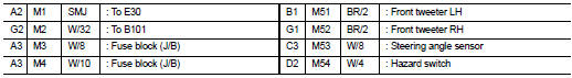
To use the grid reference
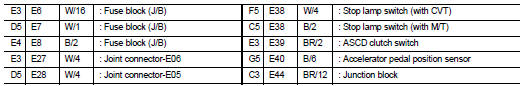
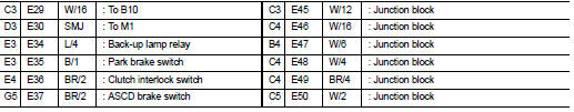
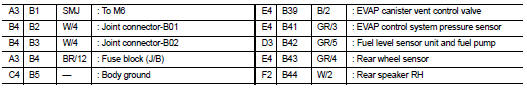
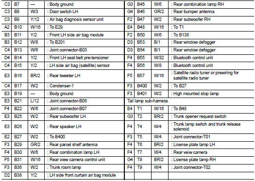
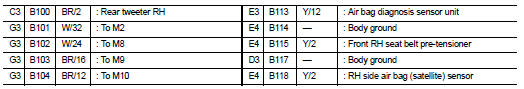
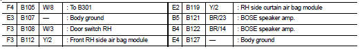
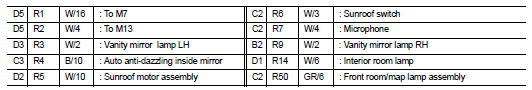
1. Find the desired connector number on the connector list.
2. Find the grid reference.
3. On the drawing, find the crossing of the grid reference letter column and number row.
4. Find the connector number in the crossing zone.
5. Follow the line (if used) to the connector.
OUTLINE
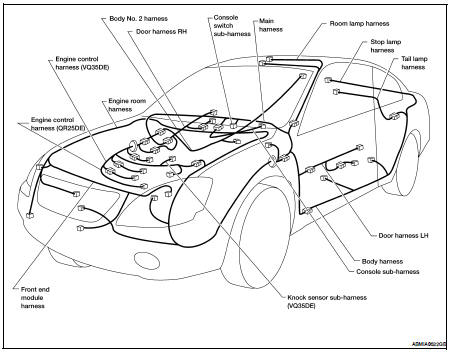
MAIN HARNESS
ENGINE ROOM HARNESS
ENGINE ROOM HARNESS (PASSENGER COMPARTMENT)
FRONT END MODULE HARNESS
ENGINE CONTROL HARNESS (VQ35DE)
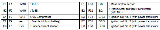
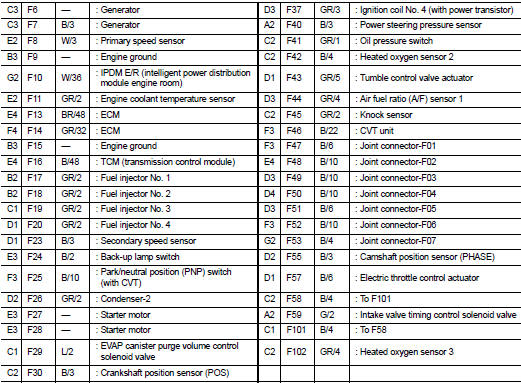
ENGINE CONTROL HARNESS (QR25DE)
BODY HARNESS
BODY NO. 2 HARNESS
ROOM LAMP HARNESS
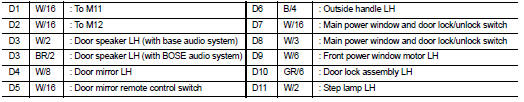
DOOR LH HARNESS
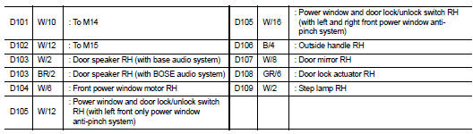
DOOR RH HARNESS
 Power supply routing circuit
 Electrical units location