Nissan Altima (L32) 2007-2012 Service Manual: Hands free phone system (sedan)
System Diagram
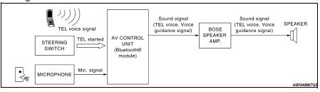
System Description
Refer to the owner's manual for Bluetooth telephone system operating instructions.
NOTE: Cellular telephones must have their wireless connection set up (paired) before using the Bluetooth telephone system.
Bluetooth telephone system allows users who have a Bluetooth cellular telephone to make a wireless connection between their cellular telephone and the AV control unit. Hands-free cellular telephone calls can be sent and received. Personal memos can be created using the Nissan Voice Recognition system. Some Bluetooth cellular telephones may not be recognized by the AV control unit. When a cellular telephone or the AV control unit is replaced, the telephone must be paired with the AV control unit. Different cellular telephones may have different pairing procedures. Refer to the cellular telephone operating manual.
AV CONTROL UNIT
When the ignition switch is turned to ACC or ON, the AV control unit will power up. During power up, the AV control unit is initialized and performs various self checks. Initialization may take up to 10 seconds. During this time the Bluetooth ON indicator will flash until initialization is complete. If a phone is present in the vehicle and paired with the AV control unit, Nissan Voice Recognition will then become active and the Bluetooth ON indicator will remain on. Bluetooth telephone functions can be turned off using the Nissan Voice Recognition system.
STEERING WHEEL AUDIO CONTROL SWITCHES
When buttons on the steering wheel audio control switch are pushed, the resistance in steering wheel audio control switch circuit changes depending on which button is pushed. The AV control unit uses this signal to perform various functions while navigating through the voice recognition system.
The following functions can be performed using the steering wheel audio control switch: • Initiate Self-Diagnosis of the Bluetooth telephone system
• Start a voice recognition session
• Answer and end telephone calls
• Adjust the volume of calls
• Record memos
MICROPHONE
The microphone is located in the roof console assembly. The microphone sends a signal to the AV control unit.
The microphone can be actively tested during self-diagnosis.
Component Parts Location
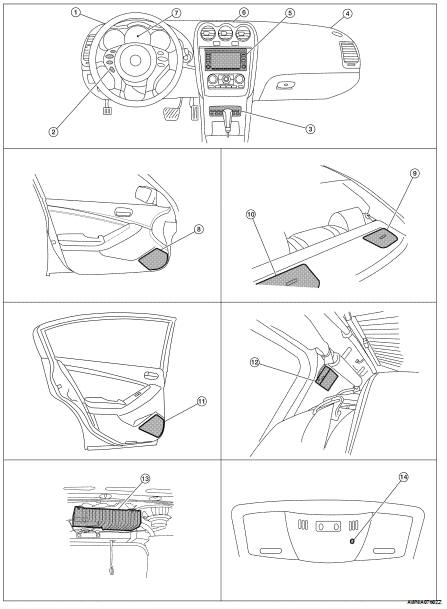
1. Tweeter LH M51
2. Steering wheel audio control switches
3. CD changer M42
4. Tweeter RH M52
5. AV control unit M46, M47, M48, M81, M90, M91
6. Center speaker M151
7. Combination meter M24
8. Front door speaker
LH D3
RH D103
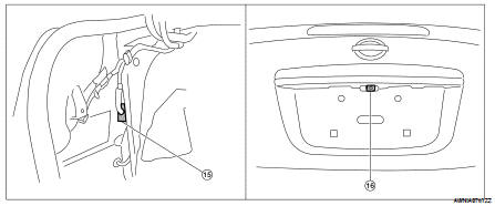
9. Rear subwoofer RH B124
10. Rear subwoofer LH B120
11. Rear door speaker
LH D202
RH D302
12. Antenna amp M502 (view with rear pillar finisher RH removed)
13. BOSE speaker amp. B121, B122
14. Microphone R7
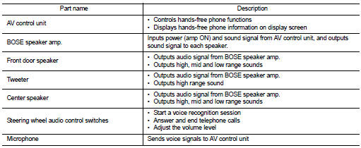
15. Rear view camera control unit B31 (view with trunk side finisher LH removed)
16. Rear view camera B35
Component Description
 Hands free phone system (coupe)
 Diagnosis system (AV control unit)