Nissan Altima (L32) 2007-2012 Service Manual: Headlamp
Aiming Adjustment
PREPARATION BEFORE ADJUSTING
NOTE: • For details, refer to the regulations in your area.
• Perform aiming adjustment if the vehicle front body has been repaired and/or the front combination lamp assembly has been replaced.
Before performing aiming adjustment, check the following.
• Adjust the tire pressure to specification.
• Position vehicle and screen on level surface.
• Ensure there is no load in vehicle other than the driver (or equivalent weight placed in driver's position).
• Ensure engine coolant and engine oil are filled to correct levels and fuel tank is full.
• Confirm spare tire, jack and tools are properly stowed.
• Wipe off dirt on the headlamp.
CAUTION: Never use organic solvent (thinner, gasoline etc.).
Aiming Adjustment procedure
1. Position the screen.
NOTE: • Stop the vehicle facing the screen.
• Place the screen on a plain road vertically.
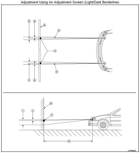
2. Face the screen with the vehicle. Maintain 7.62 m (25 ft) between the headlamp bulb center and the screen.
3. Start the engine. Turn the headlamp (LO) ON.
CAUTION: Never cover the lens surface with tape, etc. The lens is made of resin.
NOTE: • Aim each headlamp individually and ensure other headlamp beam pattern is blocked from screen.
• For horizontal aiming, adjust headlamp until beam pattern is at horizontal center point.
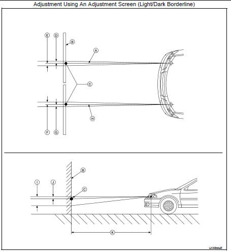
A. Headlamp beam (RH)
B. Screen
C. Horizontal/Vertical center point of headlamp
D. 66.5 mm (2.6 in)
E. 66.5 mm (2.6 in)
F. 66.5 mm (2.6 in)
G. 66.5 mm (2.6 in)
H. Headlamp beam (LH)
I. 53.2 mm (2.1 in)
J. 13.3 mm (0.5 in)
K. 7.62 m (25 ft)
Description
PREPARATION BEFORE ADJUSTING
NOTE: • For details, refer to the regulations in your area.
• Perform aiming adjustment if the vehicle front body has been repaired and/or the front combination lamp assembly has been replaced.
Before performing aiming adjustment, check the following.
• Adjust the tire pressure to specification.
• Position vehicle and screen on level surface.
• Ensure there is no load in vehicle other than the driver (or equivalent weight placed in driver's position).
• Ensure engine coolant and engine oil are filled to correct levels and fuel tank is full.
Confirm spare tire, jack and tools are properly stowed.
• Wipe off dirt on the headlamp.
CAUTION: Never use organic solvent (thinner, gasoline etc.).
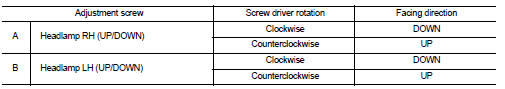
AIMING ADJUSTMENT SCREW
A. Headlamp RH (UP/DOWN) adjustment screw
B. Headlamp LH (UP/DOWN) adjustment screw

Aiming Adjustment Procedure
1. Position the screen.
NOTE: • Stop the vehicle facing the screen.
• Place the screen on a plain road vertically.
2. Face the screen with the vehicle. Maintain 7.62 m (25 ft) between the headlamp bulb center and the screen.
3. Start the engine. Turn the headlamp (LO) ON.
CAUTION: Never cover the lens surface with tape, etc. The lens is made of resin. NOTE: • Aim each headlamp individually and ensure other headlamp beam pattern is blocked from screen.
• For horizontal aiming, adjust headlamp until beam pattern is at horizontal center point.
A. Headlamp beam (RH)
B. Screen
C. Horizontal/Vertical center point of headlamp
D. 66.5 mm (2.6 in)
E. 66.5 mm (2.6 in)
F. 66.5 mm (2.6 in)
G. 66.5 mm (2.6 in)
H. Headlamp beam (LH)
I. 53.2 mm (2.1 in)
J. 13.3 mm (0.5 in)
K. 7.62 m (25 ft)
 On-vehicle maintenance
 Front fog lamp