Nissan Altima (L32) 2007-2012 Service Manual: Headlining
Exploded View
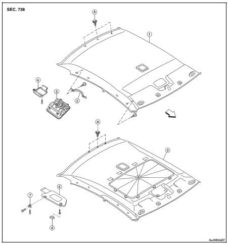
1. Headlining assembly (without sunroof)
2. Assist grip
3. Headlining assembly (with sunroof)
4. Front room/Map lamp assembly bracket
5. Front room/Map lamp assembly
6. Sunvisor
7. Sunvisor holder
8. Sunvisor cover

A. Clip C101
B. Dual lock fastener
Removal and Installation
CAUTION: • Disconnect the negative and positive battery cables.
• Be careful not to bend headlining during removal or installation.
REMOVAL
1. Recline the front seats to the fully reclined position.
2. Disconnect the negative and positive battery terminals.
3. Remove front pillar finisher (RH/LH). Refer to INT-15, "Removal and Installation".
4. Remove rear seat cushion and seatbacks. Refer to SE-25, "Removal and Installation".
5. Remove door welts (RH/LH).
6. Remove upper and lower rear pillar finishers. Refer to INT-15, "Removal and Installation".
7. Disconnect headlining harness and antenna feeder connectors.
8. Disconnect antenna amplifier and rear window defogger connectors.
9. Release the molded clip, then remove assist grips.
10. Remove the sunvisor covers and screws, and then remove sunvisors (RH/LH).
11. Insert a suitable thin tool into the sunvisor holder notch and press in to release the locking tab.
• Rotate sunvisor holder 90 degrees and pull away from headlining to remove.
12. Remove map lamp bracket and map lamp assembly.
13. For sunroof equipped vehicles, use a suitable tool to release dual lock fastener(s) around the sunroof opening and release the sunroof clip.
14. Remove rear view mirror.
15. Release the three hidden clips near the rear edge of headliner using a suitable clip removal tool.
16. Drop headlining down and carefully rotate into position. Remove headlining through door opening.
CAUTION: • When removing, two workers are required. (one for each front and rear of headlining) • Cover center console finisher upper surface with a shop cloth to prevent damage.
INSTALLATION
Installation is in the reverse order of removal.
 Floor trim
 Trunk room trim & trunk lid finisher