Nissan Altima (L32) 2007-2012 Service Manual: How to read wiring diagrams
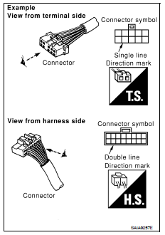
Connector symbols
Most of connector symbols in wiring diagrams are shown from the terminal side.
• Connector symbols shown from the terminal side are enclosed by a single line and followed by the direction mark.
• Connector symbols shown from the harness side are enclosed by a double line and followed by the direction mark.
• Certain systems and components, especially those related to OBD, may use a new style slide-locking type harness connector.
For description and how to disconnect, refer to PG section, “Description”, “HARNESS CONNECTOR”.
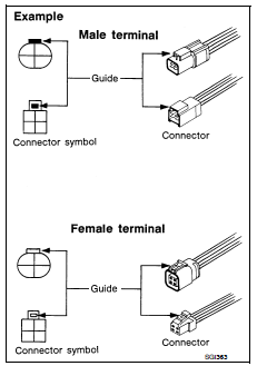
• Male and female terminals
Connector guides for male terminals are shown in black and female terminals in white in wiring diagrams.
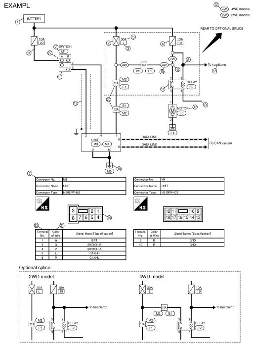
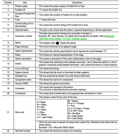
Sample/wiring diagram -example-
• For detail, refer to following GI-11, "Description".
Description
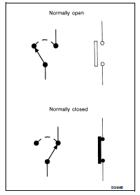
SWITCH POSITIONS
Switches are shown in wiring diagrams as if the vehicle is in the “normal” condition.
A vehicle is in the “normal” condition when:
• ignition switch is “OFF”, • doors, hood and trunk lid/back door are closed, • pedals are not depressed, and • parking brake is released.
MULTIPLE SWITCH
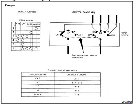
The continuity of multiple switch is described in two ways as shown below.
• The switch chart is used in schematic diagrams.
• The switch diagram is used in wiring diagrams.
 How to follow trouble diagnoses
 Abbreviations