Nissan Altima (L32) 2007-2012 Service Manual: Hydraulic line
QR25DE : Exploded View
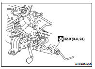
CAUTION: Securely insert harness connector to pressure sensor.
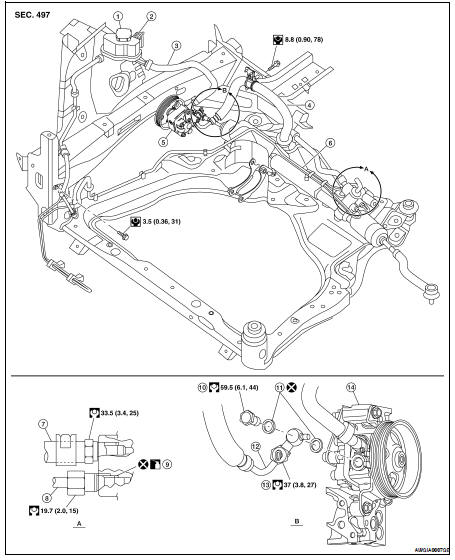
1. Reservoir tank
2. Reservoir tank bracket
3. Suction hose
4. High-pressure hose
5. Oil pump assembly
6. Steering gear assembly
7. Low pressure piping
8. High pressure piping
9. O-ring
10. Eye-bolt
11. Copper washer
12. Eye-joint (assembled to high-pressure side hose)
13. Pressure sensor
14. Oil pump bracket to engine block mounting point
QR25DE : Removal and Installation
REMOVAL
Refer to ST-21, "QR25DE : Exploded View" for removal procedure.
INSTALLATION
• Insert hose securely until it contacts tube spool.
CAUTION: Do not apply fluid.
• Install eye-bolt with eye-joint (assembled to high-pressure hose) protrusion facing with pump side cutout, and then tighten it to the specified torque after tightening by hand.
VQ35DE : With 17 Inch Tire
EXPLODED VIEW
CAUTION: Securely insert harness connector to pressure sensor.
1. Reservoir tank
2. Reservoir tank bracket
3. Suction hose
4. High pressure hose
5. Oil pump assembly
6. Steering gear assembly
7. Low pressure piping
8. High pressure piping
9. O-ring
10. Eye-bolt
11. Copper washer
12. Eye-joint (assembled to high-pressure side hose)
13. Pressure sensor
14. Oil pump bracket to engine mounting point
REMOVAL AND INSTALLATION
Removal
Refer to ST-22, "VQ35DE : With 17 Inch Tire" for removal procedure.
Installation
• Insert hose securely until it contacts tube spool. CAUTION: Do not apply fluid.
• Install eye-bolt with eye-joint (assembled to high-pressure hose) protrusion facing with pump side cutout, and then tighten it to the specified torque after tightening by hand.
VQ35DE : With 18 Inch Tire
EXPLODED VIEW
CAUTION: Securely insert harness connector to pressure sensor.
1. High pressure hose
2. Suction hose
3. Reservoir tank bracket
4. Reservoir tank
5. Oil pump assembly
6. Power steering fluid cooler
7. Power steering fluid cooler brackets
8. Steering gear assembly
9. Low pressure piping
10. Eye-bolt
11. High pressure piping
12. Copper washer
13. eye bolt
14. Copper washer
15. Pressure sensor
16. Eye-joint (assembled to high-pressure side hose)
REMOVAL AND INSTALLATION
Removal
Refer to ST-24, "VQ35DE : With 18 Inch Tire" for removal procedure.
Installation
CAUTION: Do not apply fluid.
• Install eye-bolt with eye-joint (assembled to high-pressure hose) protrusion facing with pump side cutout, and then tighten it to the specified torque after tightening by hand.
• Install check valve with eye-joint (assembled to high pressure tube) protrusion facing gear side and tighten it to the specified torque after tightening by hand.
CAUTION: Do not reuse copper washers.
 Power steering oil pump
 Disassembly and assembly