Nissan Altima (L32) 2007-2012 Service Manual: Power steering oil pump
QR25DE : Exploded View
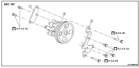
1. Rear bracket
2. Pump assembly
3. Front bracket
Removal and Installation
REMOVAL
1. Drain power steering fluid from reservoir tank.
2. Remove undercover using power tool.
3. Loosen drive belt. Refer to EM-16, "Removal and Installation".
4. Remove drive belt from oil pump pulley.
5. Remove piping of high pressure and low pressure (drain fluid from pipings). Refer to ST-21, "QR25DE : Exploded View".
6. Remove oil pump bolts, and then remove power steering oil pump. Refer to ST-19, "QR25DE : Exploded View".
INSPECTION AFTER REMOVAL
NSTALLATION
Installation is in the reverse order of removal. For tightening specifications, refer to ST-19, "QR25DE : Exploded View".
• Perform the following procedure after installing.
- For the installation of drive belt, refer to EM-16, "Tension Adjustment".
- Bleed air. Refer to ST-8, "Inspection".
VQ35DE : Exploded View
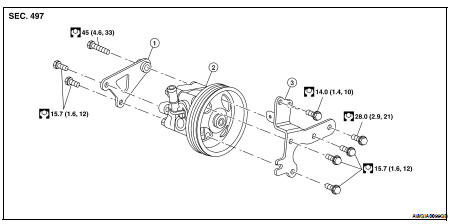
1. Rear bracket
2. Pump assembly
3. Front bracket
VQ35DE : Removal and Installation
REMOVAL
1. Drain power steering fluid from reservoir tank.
2. Remove undercover using power tool.
3. Loosen drive belt. Refer to EM-121, "Removal and Installation".
4. Remove drive belt from oil pump pulley.
5. Remove piping of high pressure and low pressure (drain fluid from pipings). Refer to ST-22, "VQ35DE : With 17 Inch Tire" or ST-24, "VQ35DE : With 18 Inch Tire".
6. Remove oil pump bolts, and then remove power steering oil pump. Refer to ST-20, "VQ35DE : Exploded View".
INSPECTION AFTER REMOVAL
INSTALLATION
Installation is in the reverse order of removal.
• When installing power steering oil pump, install all bolts by hand initially, then tighten bolts to specification.
• Perform the following procedure after installing.
- Adjust belt tension. Refer to EM-121, "Tension Adjustment".
- Bleed air. Refer to ST-8, "Inspection".
 Steering gear and linkage
 Hydraulic line