Nissan Altima (L32) 2007-2012 Service Manual: Inspection and adjustment
ADDITIONAL SERVICE WHEN REPLACING CONTROL UNIT
Service After Replacing TCM and Transaxle Assembly
Perform the applicable service in the following sheet when replacing TCM or transaxle assembly.
CAUTION: • Do not start the engine until the service is completed.
• “TCM-POWER SUPPLY [P1701]” may be indicated soon after replacing TCM or transaxle assembly (after erasing the memory at the pattern B). Restart the self-diagnosis after erasing the self-diagnosis result. Check that no error is detected.
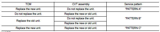
NOTE: Old unit means that the unit has been already used for another vehicle.
PATTERN A
1. Shift the selector lever to “P” position after replacing TCM. Turn ignition switch ON.
2. Check that the shift position indicator in the combination meter turns ON (It indicates approximately 1 or 2 seconds after turning the ignition switch ON.) • Check the following items if the shift position indicator does not turn ON. Repair or replace the shift position indicator if necessary.
- The harness between TCM and ROM ASSY in the transaxle assembly is open or short.
- Cable disconnected, loosen, or bent from the connector housing.
PATTERN B
1. Turn ignition switch ON after replacing each part.
2. Start engine.
CAUTION: Do not start the driving. 3. Select “DATA MONITOR”.
4. Warm up transaxle assembly until “ATFTEMP COUNT” indicates 47 [approximately 20°C (68°F)] or more.
Turn ignition switch OFF.
5. Turn ignition switch ON.
CAUTION: Do not start engine. 6. Perform “SELF-DIAG RESULTS” mode for “TRANSMISSION”.
7. Shift the selector lever to “R” position.
8. Depress slightly the accelerator pedal (Pedal angle: 2/8) while depressing the brake pedal.
9. Perform “ERASE”.
10. Shift selector lever to “R” position after replacing TCM. Turn ignition switch OFF.
11. Wait approximately 10 minutes after turning ignition switch OFF.
12. Turn ignition switch ON while shifting selector lever to “R” position.
CAUTION: Do not start engine. 13. Select “Special function”.
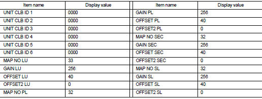
14. Check that the value on “CALIBRATION DATA” is same as the data after erasing “Calibration Data”.
• Restart the procedure from step 3 if the values are not same.
15. Shift selector lever to “P” position.
16. Check that the shift position indicator in the combination meter turns ON (It indicates approximately 1 or 2 seconds after shifting the selector lever to “P” position.) • Check the following items if the shift position indicator does not turn ON. Repair or replace the shift position indicator if necessary.
- The harness between TCM and ROM ASSY in the transaxle assembly is open or short.
- Cable disconnected, loosen, or bent from the connector housing.
- Power supply and ground of TCM. Refer to TM-349.
Calibration Data
Data after deletion
PATTERN C
1. Replace transaxle assembly first, and then replace TCM.
2. Perform the service of “PATTERN A”.
(Perform the service of “PATTERN B” if TCM is replaced first.)
 Diagnosis and repair workflow
 Function diagnosis