Nissan Altima (L32) 2007-2012 Service Manual: IPDM E/R (Intelligent power distribution module engine room)
Reference Value
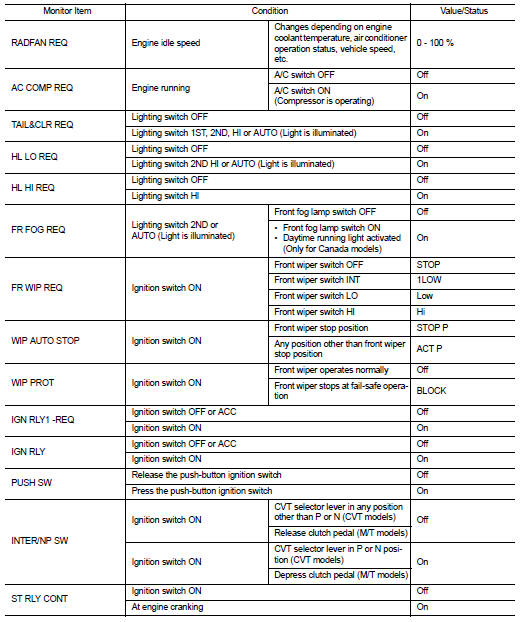
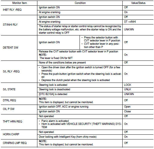
VALUES ON THE DIAGNOSIS TOOL
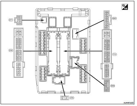
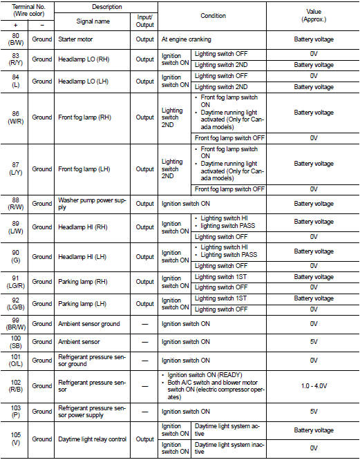
TERMINAL LAYOUT
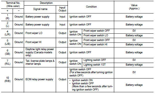
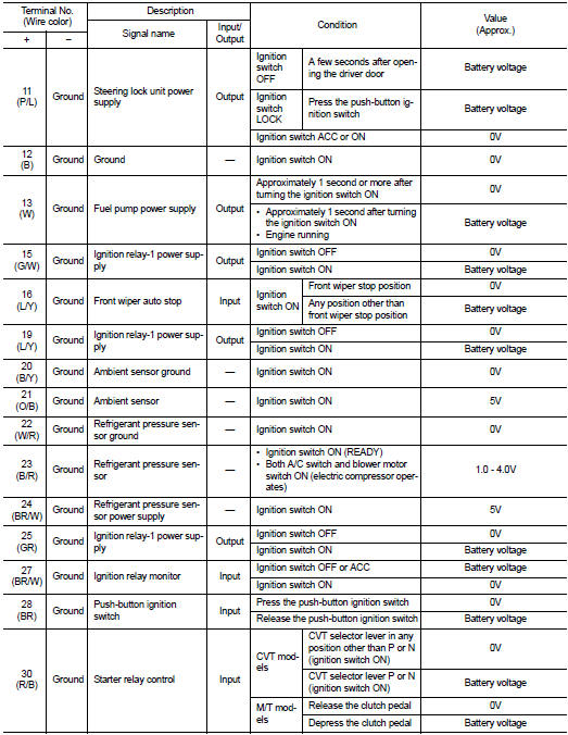
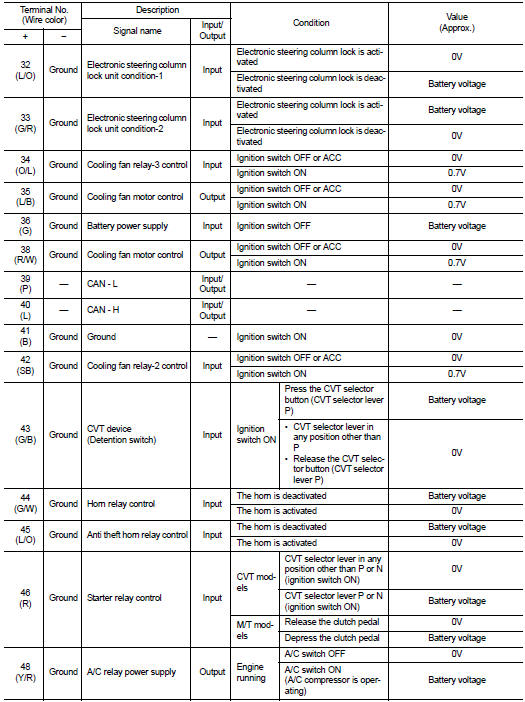
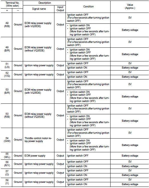
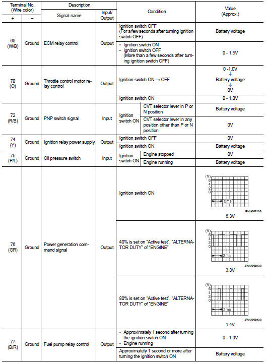
PHYSICAL VALUES
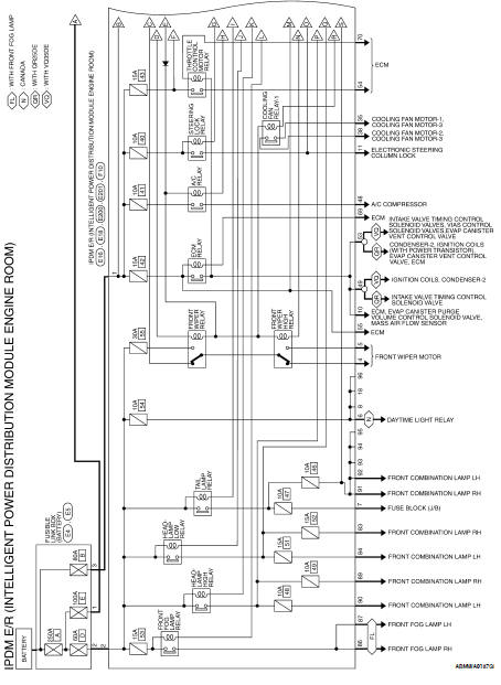
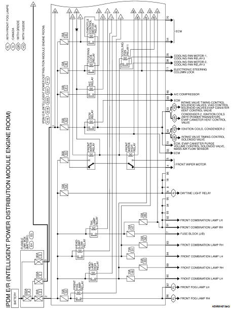
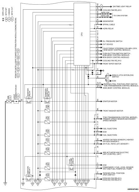
Wiring Diagram — Coupe
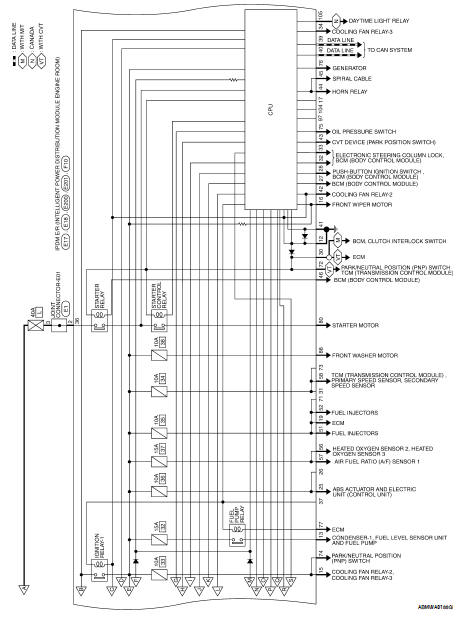
Wiring Diagram — Sedan
Fail Safe
CAN COMMUNICATION CONTROL
When CAN communication with ECM and BCM is impossible, IPDM E/R performs fail-safe control. After CAN communication recovers normally, it also returns to normal control.
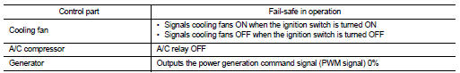
If No CAN Communication Is Available With ECM
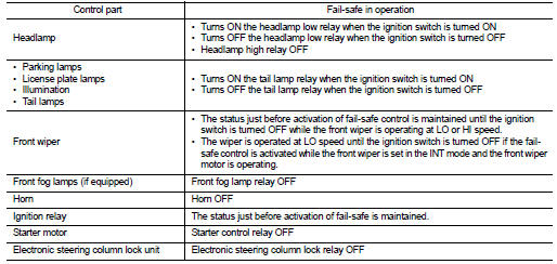
If No CAN Communication Is Available With BCM
IGNITION RELAY MALFUNCTION DETECTION FUNCTION
• IPDM E/R monitors the voltage at the contact circuit and excitation coil circuit of the ignition relay inside it.
• IPDM E/R judges the ignition relay error if the voltage differs between the contact circuit and the excitation coil circuit.
• If the ignition relay cannot turn OFF due to contact seizure, it activates the tail lamp relay for 10 minutes to alert the user to the ignition relay malfunction when the ignition switch is turned OFF.
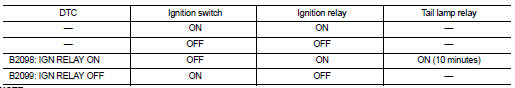
NOTE: The tail lamp turns OFF when the ignition switch is turned ON.
FRONT WIPER CONTROL
IPDM E/R detects front wiper stop position by a front wiper auto stop signal.
When a front wiper auto stop signal is in the conditions listed below, IPDM E/R stops power supply to wiper after repeating a front wiper 10 second activation and 20 second stop five times.
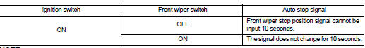
NOTE: This operation status can be confirmed on the IPDM E/R “Data Monitor” that displays “BLOCK” for the item “WIP PROT” while the wiper is stopped.
STARTER MOTOR PROTECTION FUNCTION
IPDM E/R turns OFF the starter control relay to protect the starter motor when the starter control relay remains active for 90 seconds.
DTC Index
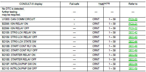
NOTE: The details of TIME display are as follows.
• CRNT: The malfunctions that are detected now
• 1 - 39: The number is indicated when it is normal at present and a malfunction was detected in the past. It increases like 0 → 1 → 2 · · · 38 → 39 after returning to the normal condition whenever IGN OFF → ON. It is fixed to 39 until the self-diagnosis results are erased if it is over 39. It returns to 0 when a malfunction is detected again in the process.
 BCM (Body control module)
 Symptom diagnosis