Nissan Altima (L32) 2007-2012 Service Manual: Microphone
Diagnosis Procedure
1.CHECK POWER SUPPLY CIRCUIT (MICROPHONE SIDE)
Check voltage between microphone harness connector and ground.
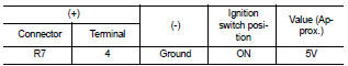
Is proper voltage present? YES >> GO TO 4
NO >> GO TO 2
2.CHECK POWER SUPPLY CIRCUIT (CONTINUITY)
1. Turn ignition switch OFF.
2. Disconnect microphone and AV control unit harness connectors.
3. Check continuity between microphone harness connector R7 (A) terminal 4 and AV control unit harness connector M46 (B) terminal 46.

4. Check continuity between microphone harness connector R7 (A) terminal 4 and ground.

Are the continuity test results as specified? YES >> GO TO 3
NO >> Repair harness or connector.
3.CHECK POWER SUPPLY CIRCUIT (AV CONTROL UNIT SIDE)
1. Connect AV control unit harness connector.
2. Turn ignition switch to ACC.
3. Check voltage between AV control unit harness connector and ground.
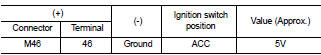
1. Connect AV control unit harness connector.
2. Turn ignition switch to ACC.
3. Check voltage between AV control unit harness connector and ground.
4.CHECK GROUND CIRCUIT
1. Turn ignition switch OFF.
2. Disconnect microphone harness connector R7 and AV control unit harness connector M46.
3. Check continuity between microphone harness connector R7 (A) terminal 2 and AV control unit harness connector M46 (B) terminal 47.

Does continuity exist? YES >> Inspection End.
NO >> Repair harness or connector.
 CD changer
 Power supply and ground circuit
(sedan)
Power supply and ground circuit
(sedan)