Nissan Altima (L32) 2007-2012 Service Manual: Navigation system (sedan)
System Diagram
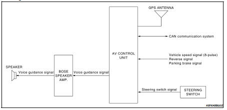
System Description
NOTE: Refer to NAVI System Owner's Manual for system operation.
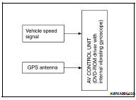
The navigation system periodically calculates the vehicle's current position according to the following three signals: Travel distance of the vehicle as determined by the vehicle speed sensor, turning angle of the vehicle as determined by the gyroscope (angular velocity sensor), and the direction of vehicle travel as determined by the GPS antenna (GPS information).
The current position of the vehicle is then identified by comparing the calculated vehicle position with map data read from the map DVDROM, which is stored in the DVD-ROM drive (map-matching), and indicated on the screen with a current-location mark.
By comparing the vehicle position detection results found by the GPS and by map-matching, more accurate vehicle position data can be used.
The current vehicle position will be calculated by detecting the distance the vehicle moved from the previous calculation point and its direction.
TRAVEL DISTANCE
Travel distance calculations are based on the vehicle speed input signal. Therefore, the calculation may become incorrect as the tires wear down. To prevent this, an automatic distance fine adjustment function has been adopted.
TRAVEL DIRECTION
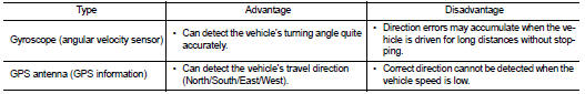
Change in the travel direction of the vehicle is calculated by a gyroscope (angular velocity sensor) and a GPS antenna (GPS information). As the gyroscope and GPS antenna have both merit and demerit, input signals
from them are prioritized in each situation. However, this order of priority may change in accordance with more detailed travel conditions so that the travel direction is detected more accurately.
MAP–MATCHING
Map–matching is a function that repositions the vehicle on the road map when a new location is judged to be the most accurate. This is done by comparing the current vehicle position, calculated by the method described in the position detection principle, with the road map data around the vehicle, read from the map DVD-ROM stored in the DVD-ROM drive.
Therefore, the vehicle position may not be corrected after the vehicle is driven over a certain distance or time in which GPS information is hard to receive. In this case, the current-location mark on the display must be corrected manually.
CAUTION: The road map data is based on data stored in the map DVDROM.
• In map-matching, alternative routes to reach the destination will be shown and prioritized, after the road on which the vehicle is currently driven has been judged and the current-location mark has been repositioned.
If there is an error in distance and/or direction, the alternative routes will be shown in different order of priority, and the wrong road can be avoided.
If two roads are running in parallel, they are of the same priority.
Therefore, the current-location mark may appear on either of them alternately, depending on maneuvering of the steering wheel and configuration of the road.
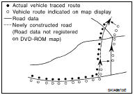
• Map-matching does not function correctly when the road on which the vehicle is driving is new and not recorded in the map DVDROM, or when the road pattern stored in the map data and the actual road pattern are different due to repair.
When driving on a road not present in the map, the map-matching function may find another road and position the current-location mark on it. Then, when the correct road is detected, the currentlocation mark may leap to it.
• Effective range for comparing the vehicle position and travel direction calculated by the distance and direction with the road data read from the map DVD-ROM is limited. Therefore, when there is an excessive gap between the current vehicle position and the position on the map, correction by map-matching is not possible.
GPS (GLOBAL POSITIONING SYSTEM)
GPS (Global Positioning System) has been developed and controlled by the US Department of Defense. The system utilizes GPS satellite (NAVSTAR), sending out radio waves while flying on an orbit around the earth at the height of approx. 21,000 km (13,000 miles).
The GPS receiver calculates the vehicle's position in three dimensions (latitude/longitude/altitude) according to the time lag of the radio waves received from four or more GPS satellites (three-dimensional positioning). If radio waves were received only from three GPS satellites, the GPS receiver calculates the vehicle's position in two dimensions (latitude/longitude), utilizing the altitude data calculated previously by using radio waves from four or more GPS satellites (two-dimensional positioning).
Accuracy of the GPS will deteriorate under the following conditions.
• In two-dimensional positioning, the GPS accuracy will deteriorate when the altitude of the vehicle position changes.
• There may be an error of approximately 10 m (30 ft.) in position detected by three-dimensional positioning, which is more accurate than two-dimensional positioning. The accuracy can be even lower depending on the arrangement of the GPS satellites utilized for the positioning.
• Position detection is not possible when the vehicle is in an area where radio waves from the GPS satellite do not reach, such as in a tunnel, parking lot in a building, and under an elevated highway. Radio waves from the GPS satellites may not be received when some object is located over the GPS antenna.
• Position correction by GPS is not available while the vehicle is stopped.
Component Parts Location
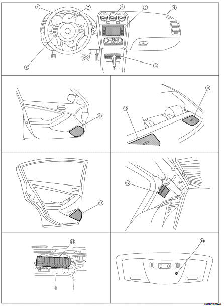
1. Tweeter LH M51
2. Steering wheel audio control switches
3. CD changer M42
4. Tweeter RH M52
5. AV control unit M46, M47, M48, M81, M90, M91
6. Center speaker M151
7. Combination meter M24
8. Front door speaker
LH D3
RH D103
9. Rear subwoofer RH B124
10. Rear subwoofer LH B120
11. Rear door speaker
LH D202
RH D302
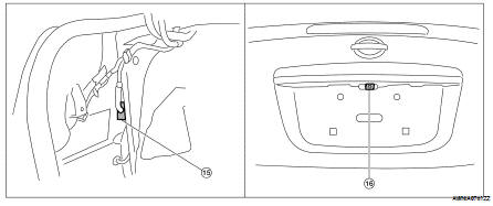
12. Antenna amp M502 (view with rear pillar finisher RH removed)
13. BOSE speaker amp. B121, B122
14. Microphone R7
15. Rear view camera control unit B31 (view with trunk side finisher LH removed)
16. Rear view camera B35
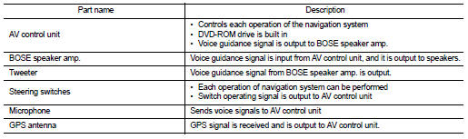
Component Description
 Navigation system (coupe)
 Rear view monitor system (coupe)