Nissan Altima (L32) 2007-2012 Service Manual: NVIS (Nissan vehicle immobilizer system- nats)
System Diagram
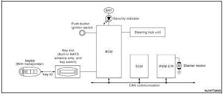
System Description
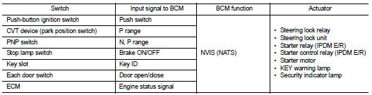
INPUT/OUTPUT SIGNAL CHART
SYSTEM DESCRIPTION
• The NVIS (NATS) is an anti-theft system by registering a keyfob ID in to the vehicle and prevents the engine being started by an unregistered keyfob. It has a higher protection against auto thefts that duplicate mechanical key.
• It performs the ID verification when starting the engine in the same way as the remote keyless entry system.
But, it performs the NVIS (NATS) ID verification when inserting the keyfob and performs the keyfob ID verification when carrying the keyfob.
• The remote keyless entry system of L32 is not the same as the conventional models. The mechanical key integrated in the keyfob cannot start the engine. When the keyfob battery is discharged, the NVIS (NATS) ID verification memorized to the transponder integrated with keyfob is performed by inserting the keyfob into the key slot. If the verification results are OK, the engine start operation can be performed by the push-button ignition switch operation.
• Locate the security indicator and apply the anti-theft system equipment sticker, forewarn that the NVIS (NATS) is onboard with the model.
• The security indicator always blinks when the keyfob is removed from the key slot and when the power supply position is in LOCK position.
• Keyfob can be registered up to 4 keys (Including the standard ignition key) on request from the owner.
• The specified registration is required when replacing ECM, BCM or keyfob. The registrations procedure for NVIS (NATS) and registration procedure for keyfob when installing the BCM, refer to CONSULT-III Operation Manual.
• Possible symptom of NVIS (NATS) malfunction is “Engine cannot start”. In L32, the engine can be started with the remote keyless entry system and NVIS (NATS). Identify the possible causes according to “Work Flow”, Refer to SEC-411, "Work Flow".
• If ECM other than Genuine NISSAN is installed, the engine cannot be started. For ECM replacement procedure, refer to SEC-416, "ECM RE-COMMUNICATING FUNCTION : Special Repair Requirement".
PRECAUTIONS FOR KEY REGISTRATION
• The key registration is a procedure that erases the current NVIS (NATS) ID once, and then re-registers a new ID operation. Therefore the registered keyfob is necessary for this procedure. Before starting the registration operation collect all registered keyfobs from the customer • When registering the keyfob, performs only one procedure to register simultaneously both ID (NVIS “NATS” ID registration and keyfob ID registration).
The NVIS (NATS) ID registration is the procedure that registers the ID stored into the transponder (integrated in keyfob) to BCM.
The keyfob ID registration is the procedure that registers the ID to BCM.
• When performing the keyfob registration only, the engine cannot be started by inserting the key into the key slot. When performing the NVIS (NATS) registration only, the engine cannot be started by the operation when carrying the key. The registrations of both systems should be performed.
SECURITY INDICATOR
• Warns that the vehicle is equipped with NVIS (NATS).
• The security indicator always blinks when the keyfob is removed from the key slot and when the ignition switch is in LOCK position.
NOTE: Because security indicator is highly efficient, the battery is barely affected.
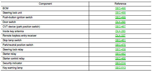
Component Parts Location
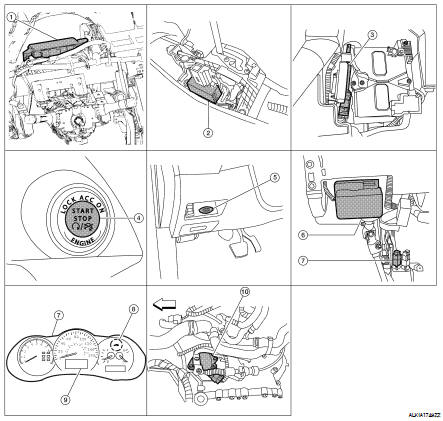
1. Body control module M16, M17, M18, M19, M21 (view with instrument panel removed)
2. CVT device (park position switch) M23
3. ECM E10
4. Push button ignition switch M38
5. Key slot M40
6. Electronic steering column lock M32 (steering column)
7. Stop lamp switch E38 (view with lower LH instrument panel removed)
8. Security indicator lamp
9. Information display
10. Park neutral position switch F25
Component Description
 Engine start function
 Vehicle security system