Nissan Altima (L32) 2007-2012 Service Manual: Vehicle security system
System Diagram
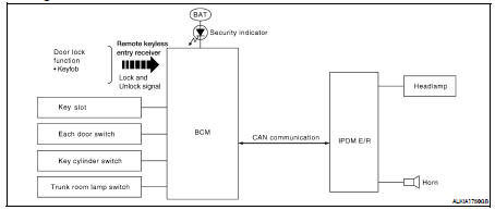
System Description
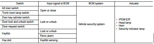
INPUT/OUTPUT SIGNAL CHART
OPERATION FLOW
SETTING THE VEHICLE SECURITY SYSTEM
Initial Condition
• Ignition switch is in OFF position.
Disarmed Phase
• When doors or trunk is open, the vehicle security system is set in the disarmed phase on the assumption that the owner is inside or near the vehicle.
• When the vehicle security system is in the disarmed phase, the security indicator lamp blinks every 2.4 seconds.
Pre-armed Phase and Armed Phase
When the following operation 1 or 2 is performed, the vehicle security system turns into the “pre-armed” phase. (The security indicator lamp illuminates.) 1. BCM receives LOCK signal from front door key cylinder switch or keyfob, after trunk and all doors are closed.
2. Trunk and all doors are closed after front doors are locked by key or door lock and unlock switch.
The security indicator lamp illuminates for 30 seconds. Then, the system automatically shifts into the “armed” phase.
CANCELING THE SET VEHICLE SECURITY SYSTEM
When one of the following operations is performed, the armed phase is canceled.
1. Unlock the doors with the key or keyfob.
2. Turn ignition switch “ON” or “ACC” position.
CANCELING THE ALARM OPERATION OF THE VEHICLE SECURITY SYSTEM
When unlocking the door with the key or keyfob the alarm operation is canceled.
ACTIVATING THE ALARM OPERATION OF THE VEHICLE SECURITY SYSTEM
Check that the system is in the armed phase. (The security indicator lamp blinks every 2.4 seconds.) When the following operation 1 or 2 is performed, the system sounds the horns and flashes the headlamps for about 50 seconds.
1. Trunk or any door is opened during armed phase.
2. Disconnecting and connecting the battery connector before canceling armed phase.
PANIC ALARM OPERATION
Keyfob will not operate horn and headlamps if the ignition switch is in the ACC or ON position.
When the vehicle security system is triggered, ground is supplied intermittently to both headlamp relay and horn relay.
When headlamp relay and horn relay are energized, then power is supplied to headlamps (LH and RH) and horns (HIGH and LOW).
The headlamp flashes and the horn sounds intermittently.
The alarm automatically turns off after 50 seconds or when BCM receives any signal from keyfob.
Component Parts Location
1. Body control module M16, M17, M18, M19, M21 (view with instrument panel removed)
2. IPDM E/R E17, E18, F10
3. Horn relay H-1
4. Key slot M40
5. Remote keyless entry receiver M27 (view with instrument panel removed)
6. Main power window and door lock/ unlock switch D7, D8
7. Power window and door lock/unlock switch RH D105
8. Front door lock assembly LH (key cylinder switch) D10
9. Front door switch LH B8 RH B108
10. Rear door switch LH B18 RH B108
11. Trunk lamp switch and trunk release solenoid B28
12. Horn E216 (view with front fender protector LH removed)
13. Combination meter M24
14. Security indicator lamp
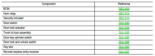
Component Description
 NVIS (Nissan vehicle immobilizer system- nats)
 Diagnosis system (BCM)