Nissan Altima (L32) 2007-2012 Service Manual: Oil filter
Removal and Installation
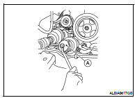
REMOVAL
1. Remove the engine undercover.
2. Remove the oil filter using Tool (A) as shown.
Tool number : KV10115801 (J-38956)
WARNING: • Be careful not to get burned, the engine and engine oil may be hot.
CAUTION: • When removing, prepare a shop cloth to absorb any oil leakage or spillage.
• Do not allow engine oil to adhere to the drive belts.
• Completely wipe off any oil that adheres to the engine and the vehicle.
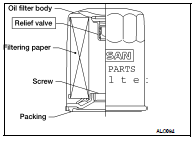
• The oil filter has a built in pressure relief valve. Use a genuine NISSAN oil filter or equivalent
INSTALLATION
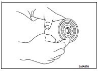
1. Remove foreign materials adhering to the oil filter installation surface.
2. Apply clean engine oil to the oil seal contact surface of the new oil filter.
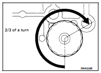
3. Screw the oil filter manually until it touches the installation surface, then tighten it by 2/3 turn. Or tighten to specification below.

4. Check the oil level and add engine oil as necessary. Refer to LU-23.
5. After warming up the engine, check for any engine oil leaks.
 Engine oil
 On-vehicle repair