Nissan Altima (L32) 2007-2012 Service Manual: On-vehicle repair
INSTRUMENT PANEL ASSEMBLY
Exploded View
1. Center speaker grille
2. Tweeter speaker grille (LH)
3. Instrument panel
4. Instrument side mask (LH)
5. Combination meter
6. Lower knee protector (LH)
7. Cluster lid A
8. Instrument lower cover (LH)
9. Fuse block cover
10. Steering column cover upper
11. Steering column cover lower
12. Console side finisher (LH)
13. CD changer finisher (if equipped)
14. Storage bin (if equipped)
15. Cup holder M/T
16. Cup holder CVT
17. Console screw cover (LH)
18. Console rear finisher (if equipped with rear duct)
19. Console rear finisher (without rear duct)
20. Console screw cover (RH)
21. CVT finisher
22. Console
23. M/T finisher
24. Console side finisher (RH)
25. Cluster lid D
26. Cluster lid C
27. Center ventilator grilles
28. Glove box assembly
29. Instrument side mask (RH)
30. Tweeter speaker grille (RH)


Removal and Installation
CAUTION: • Disconnect both battery terminals.
• Never tamper with or force air bag lid open, as this may adversely affect air bag performance.
• Be careful not to scratch instrument panel pad and other parts.
REMOVAL
1. Disconnect both battery terminals.
2. Remove the A-pillar finishers. Refer to INT-15, "Removal and Installation".
3. Put selector lever in the drive (D) position, then remove selector lever knob (CVT Models only). Refer to TM-255, "Removal and Installation".
4. Put the shift lever in neutral, then remove shift lever knob. (M/T Models only) Refer to TM-21, "Removal and Installation".
5. Remove the cluster lid D (1).
6. Remove console finisher. Refer to TM-255, "Removal and Installation".
7. Remove the storage bin (1) or CD changer finisher (if equipped).
8. Remove both instrument side masks (1).
9. Open the fuse block cover, remove the instrument lower cover screw (A), then remove the instrument lower cover (1).
• Disconnect the harness connectors.
• Disconnect the aspirator tube.
10. Remove both the console side finishers.
11. Remove the console upper screws (A).
12. Remove the console side screws (A).
13. Remove both the console rear screw covers, then remove the rear screws (A), then remove the console assembly.
14. Open the glove box door (1), remove the glove box assembly screws (A).
15. Remove the glove box assembly lower screws (A), then remove the glove box assembly.
16. Remove the steering wheel. Refer to ST-13, "Removal and Installation".
17. Remove the steering column screws (A), then remove both the steering wheel column upper (1) and lower (2) covers.
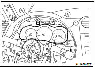
18. Remove the cluster lid A (1).
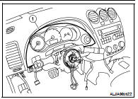
19. Remove the combination meter screws (A), then remove the combination meter (1).
• Disconnect the harness connector.
20. Remove the spiral cable. Refer to SR-8, "Removal and Installation".
21. Remove the combination switch. Refer to WW-121, "Removal and Installation".
22. Remove the center ventilator grilles (1).

23. Remove the cluster lid C assembly upper and lower screws (A), then remove the cluster lid C assembly (1).
• Disconnect the harness connectors.
24. Remove both tweeter speaker grilles and disconnect the harness connectors.
25. Remove the passenger air bag bolt (A).
26. Remove the remaining instrument panel screws (A).
27. Disconnect the audio harness connector located near the RH A-pillar.
28. Lift the instrument panel high enough in order to disconnect all the necessary harness connectors, then remove the instrument panel.
INSTALLATION
Installation is in the reverse order of removal.
• If replacing the Instrument panel transfer all the necessary parts to the new instrument panel.
 Symptom diagnosis
 Disassembly and assembly