Nissan Altima (L32) 2007-2012 Service Manual: On-vehicle repair
STARTER MOTOR
Removal and Installation
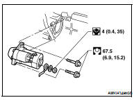
M/T MODELS
Removal
1. Disconnect the negative battery terminal.
2. Disconnect the starter motor harness connectors.
3. Remove the two starter motor bolts, using power tools.
4. Remove the starter motor.
Installation
Installation is in the reverse order of removal.
Removal and Installation
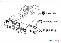
CVT Models
REMOVAL
1. Remove the battery and battery tray bracket. For Sedan Refer to PG-139, "Removal and Installation" For Coupe Refer to PG-68, "Removal and Installation" 2. Remove the air cleaner assembly ducts.
3. Disconnect the following: • ECM
• TCM
4. Disconnect the starter motor harness connectors.
5. Remove the two starter motor bolts, using power tools.
6. Remove the starter motor.
INSTALLATION
Installation is in the reverse order of removal.
Disassembly and Assembly
DISASSEMBLY
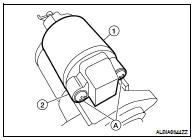
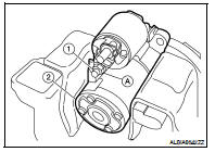
1. Set the starter motor assembly (2) onto a suitable tool using a soft cloth as shown.
2. Remove the terminal "M" nut (A) from terminal "M" (1).
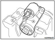
3. Disconnect terminal "M" connector (1).
4. Remove the two magnet switch assembly screws (A) and remove the magnet switch assembly (1).
CAUTION: Magnet switch assembly (1) may pop out from starter motor assembly (2) while loosening magnet switch assembly screws.
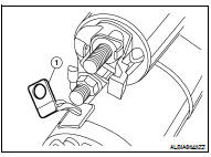
ASSEMBLY
1. Install magnet switch assembly (3) onto starter motor assembly (1).
• Pull rod (5) of magnet switch assembly (3) should be engaged with shift lever (4) as shown. CAUTION: • Do not damage the sliding surface (2) of magnet switch assembly (3).
• Do not leave any dirt on the sliding surface (2) of the magnet switch assembly (3).
• Confirm the terminal location.
2. Tighten the two magnet switch assembly screws (A) to specification.
• Magnetic switch assembly (1) • Starter motor assembly (2)
3. Connect the terminal "M" connector and tighten terminal "M" nut (A) to specification.
• Starter motor assembly (2)
CAUTION: The connector for terminal "M" (1) may rotate easily while tightening terminal "M" nut (A). Hold the connector in place while tightening terminal "M" nut (A).

 Preparation
 Service data and specifications
(SDS)
Service data and specifications
(SDS)