Nissan Altima (L32) 2007-2012 Service Manual: P0112, P0113 iat sensor
Description
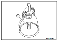
The intake air temperature sensor is built-into mass air flow sensor (1). The sensor detects intake air temperature and transmits a signal to the ECM.
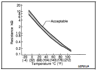
The temperature sensing unit uses a thermistor which is sensitive to the change in temperature. Electrical resistance of the thermistor decreases in response to the temperature rise.
<Reference data>
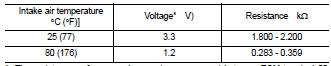
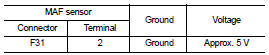
*: These data are reference values and are measured between ECM terminal 50 (Intake air temperature sensor) and ground.
CAUTION: Do not use ECM ground terminals when measuring input/output voltage. Doing so may result in damage to the ECM's transistor. Use a ground other than ECM terminals, such as the ground.
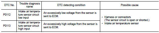
DTC Logic
DTC DETECTION LOGIC
DTC CONFIRMATION PROCEDURE
1.PRECONDITIONING
If DTC Confirmation Procedure has been previously conducted, always turn ignition switch OFF and wait at least 10 seconds before conducting the next test.
>> GO TO 2.
2.PERFORM DTC CONFIRMATION PROCEDURE
1. Turn ignition switch ON and wait at least 5 seconds.
2. Check 1st trip DTC.
Is 1st trip DTC detected? YES >> Go to EC-182, "Diagnosis Procedure".
NO >> INSPECTION END
Diagnosis Procedure
1.CHECK GROUND CONNECTION
1. Turn ignition switch OFF.
2. Check ground connection E9. Refer to Ground Inspection in GI-45, "Circuit Inspection".
Is the inspection result normal? YES >> GO TO 2.
NO >> Repair or replace ground connection.
2.CHECK INTAKE AIR TEMPERATURE SENSOR POWER SUPPLY CIRCUIT
1. Disconnect mass air flow sensor (with intake air temperature sensor) harness connector.
2. Turn ignition switch ON.
3. Check the voltage between mass air flow sensor harness connector and ground.
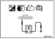
Is the inspection result normal? YES >> GO TO 3.
NO >> Repair open circuit or short to ground or short to power in harness or connectors.
3.CHECK INTAKE AIR TEMPERATURE SENSOR GROUND CIRCUIT FOR OPEN AND SHORT
1. Turn ignition switch OFF.
2. Disconnect ECM harness connector.
3. Check the continuity between mass air flow sensor harness connector and ECM harness connector.
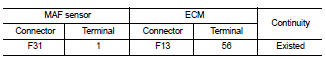
4. Also check harness for short to ground and short to power.
Is the inspection result normal? YES >> GO TO 4.
NO >> Repair open circuit or short to ground or short to power in harness or connectors.
4.CHECK INTAKE AIR TEMPERATURE SENSOR
Refer to EC-182, "Component Inspection".
Is the inspection result normal? YES >> GO TO 5.
NO >> Replace mass air flow sensor (with intake air temperature sensor).
5.CHECK INTERMITTENT INCIDENT
Refer to GI-42, "Intermittent Incident".
>> INSPECTION END
Component Inspection
1.CHECK INTAKE AIR TEMPERATURE SENSOR
1. Turn ignition switch OFF.
2. Disconnect mass air flow sensor harness connector.
3. Check resistance between mass air flow sensor terminals as follows.
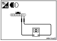
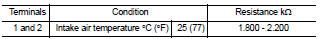
Is the inspection result normal? YES >> INSPECTION END
NO >> Replace mass air flow sensor (with intake air temperature sensor).
 P0102, P0103 maf sensor
 P0116 ect sensor