Nissan Altima (L32) 2007-2012 Service Manual: P0116 ECT sensor
Description
The engine coolant temperature sensor is used to detect the engine coolant temperature. The sensor modifies a voltage signal from the ECM. The modified signal returns to the ECM as the engine coolant temperature input. The sensor uses a thermistor which is sensitive to the change in temperature. The electrical resistance of the thermistor decreases as temperature increases.
<Reference data>
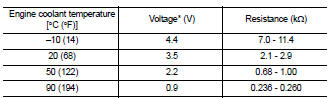
*: These data are reference values and are measured between ECM terminals 46 (Engine coolant temperature sensor) and 52 (Sensor ground).
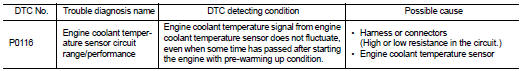
DTC Logic
DTC DETECTION LOGIC
NOTE: If DTC P0116 is displayed with P0117 or P0118, first perform the trouble diagnosis for DTC P0117, P0118. Refer to EC-1212, "DTC Logic".
DTC CONFIRMATION PROCEDURE
1.PRECONDITIONING
If DTC Confirmation Procedure has been previously conducted, always perform the following before conducting the next test.
1. Turn ignition switch OFF and wait at least 10 seconds.
2. Turn ignition switch ON.
3. Turn ignition switch OFF and wait at least 10 seconds.
TEST CONDITION: Before performing the following procedure, do not add fuel.
>> GO TO 2.
2.PERFORM DTC CONFIRMATION PROCEDURE
1. Start engine and warm it up to normal operating temperature.
2. Rev engine up to 2,000 rpm for more than 10 minutes.
3. Move the vehicle to a cool place, then stop engine and turn ignition switch OFF
4. Check resistance between “fuel level sensor unit and fuel pump” terminals 4 and 5.
5. Soak the vehicle until the resistance between “fuel level sensor unit and fuel pump” terminals 4 and 5 becomes 0.5 kΩ higher than the value measured before soaking.
CAUTION: Never turn ignition switch ON during soaking.
NOTE: Soak time changes depending on ambient air temperature. It may take several hours.
6. Start engine and let it idle for 5 minutes.
7. Check 1st trip DTC.
Is 1st trip DTC detected? YES >> EC-1211, "Diagnosis Procedure" NO >> INSPECTION END
Diagnosis Procedure
1.CHECK GROUND CONNECTION
1. Turn ignition switch OFF.
2. Check ground connection E9. Refer to Ground Inspection in GI-45, "Circuit Inspection".
Is the inspection result normal? YES >> GO TO 2.
NO >> Repair or replace ground connection.
2.CHECK ENGINE COOLANT TEMPERATURE SENSOR
Refer to EC-1211, "Component Inspection".
Is the inspection result normal? YES >> GO TO 3.
NO >> Replace engine coolant temperature sensor.
3.CHECK INTERMITTENT INCIDENT
Refer to GI-42, "Intermittent Incident".
>> INSPECTION END
Component Inspection
1.CHECK ENGINE COOLANT TEMPERATURE SENSOR
1. Turn ignition switch OFF.
2. Disconnect engine coolant temperature sensor harness connector.
3. Remove engine coolant temperature sensor.
4. Check resistance between engine coolant temperature sensor terminals as per the following.
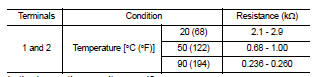
Is the inspection result normal? YES >> INSPECTION END
NO >> Replace engine coolant temperature sensor.
 P0112, P0113 IAT sensor
 P0117, P0118 ECT sensor