Nissan Altima (L32) 2007-2012 Service Manual: P0125 ECT sensor
Description
The engine coolant temperature sensor is used to detect the engine coolant temperature. The sensor modifies a voltage signal from the ECM. The modified signal returns to the ECM as the engine coolant temperature input. The sensor uses a thermistor which is sensitive to the change in temperature. The electrical resistance of the thermistor decreases as temperature increases.
<Reference data>
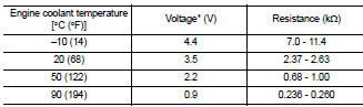
*: These data are reference values and are measured between ECM terminals 46 (Engine coolant temperature sensor) and ground.
CAUTION: Do not use ECM ground terminals when measuring input/output voltage. Doing so may result in damage to the ECM's transistor.
Use a ground other than ECM terminals, such as the ground.
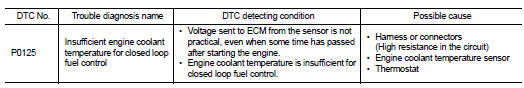
DTC Logic
DTC DETECTION LOGIC
NOTE: • If DTC P0125 is displayed with P0117 or P0118, first perform the trouble diagnosis for DTC P0117 or P0118. Refer to EC-186, "DTC Logic".
• If DTC P0125 is displayed with P0116, first perform the trouble diagnosis for DTC P0116. Refer to EC- 184, "DTC Logic".
DTC CONFIRMATION PROCEDURE
1.PRECONDITIONING
If DTC Confirmation Procedure has been previously conducted, always turn ignition switch OFF and wait at least 10 seconds before conducting the next test.
>> GO TO 2.
2.CHECK ENGINE COOLANT TEMPERATURE SENSOR FUNCTION

1. Turn ignition switch ON.
2. Select “DATA MONITOR” mode with CONSULT-III.
3. Check that “COOLAN TEMP/S” is above 5°C (41°F).

Follow the procedure “With CONSULT-III” above.
Is it above 5°C (41°F)? YES >> INSPECTION END
NO >> GO TO 3.
3.PERFORM DTC CONFIRMATION PROCEDURE

1. Start engine and run it for 65 minutes at idle speed.
2. Check 1st trip DTC.
If “COOLAN TEMP/S” increases to more than 5°C (41°F) within 65 minutes, stop engine because the test result will be OK.
CAUTION: Be careful not to overheat engine.

Follow the procedure “With CONSULT-III” above.
Is 1st trip DTC detected? YES >> EC-193, "Diagnosis Procedure" NO >> INSPECTION END
Diagnosis Procedure
1.CHECK GROUND CONNECTION
1. Turn ignition switch OFF.
2. Check ground connection E9. Refer to Ground Inspection in GI-45, "Circuit Inspection".
Is the inspection result normal? YES >> GO TO 2.
NO >> Repair or replace ground connection.
2.CHECK ENGINE COOLANT TEMPERATURE SENSOR
Refer to EC-193, "Component Inspection".
Is the inspection result normal? YES >> GO TO 3.
NO >> Replace engine coolant temperature sensor.
3.CHECK THERMOSTAT OPERATION
When the engine is cold [lower than 70°C (158°F)] condition, grasp lower radiator hose and confirm the engine coolant does not flow.
Is the inspection result normal? YES >> GO TO 4.
NO >> Repair or replace thermostat. Refer to CO-21, "Removal and Installation".
4.CHECK INTERMITTENT INCIDENT
Refer to GI-42, "Intermittent Incident".
>> INSPECTION END
Component Inspection
1.CHECK ENGINE COOLANT TEMPERATURE SENSOR
1. Turn ignition switch OFF.
2. Disconnect engine coolant temperature sensor harness connector.
3. Remove engine coolant temperature sensor.
4. Check resistance between engine coolant temperature sensor terminals as follows.
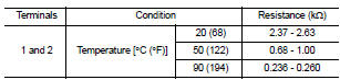
Is the inspection result normal? YES >> INSPECTION END
NO >> Replace engine coolant temperature sensor.
 P0122, P0123 TP sensor
 P0127 IAT sensor