Nissan Altima (L32) 2007-2012 Service Manual: P0327, P0328, P0332, P0333 KS
Description
The knock sensor is attached to the cylinder block. It senses engine knocking using a piezoelectric element. A knocking vibration from the cylinder block is sensed as vibrational pressure. This pressure is converted into a voltage signal and sent to the ECM.
DTC Logic
DTC DETECTION LOGIC
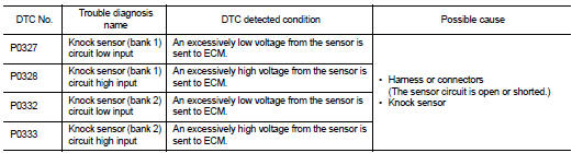
DTC CONFIRMATION PROCEDURE
1.PRECONDITIONING
If DTC Confirmation Procedure has been previously conducted, always perform the following before conducting the next test.
1. Turn ignition switch OFF and wait at least 10 seconds.
2. Turn ignition switch ON.
3. Turn ignition switch OFF and wait at least 10 seconds.
TESTING CONDITION: Before performing the following procedure, confirm that battery voltage is more than 10 V at idle.
>> GO TO 2.
2.PERFORM DTC CONFIRMATION PROCEDURE
1. Start engine and run it for at least 5 seconds at idle speed.
2. Check 1st trip DTC.
Is 1st trip DTC detected? YES >> Go to EC-1289, "Diagnosis Procedure".
NO >> INSPECTION END
Diagnosis Procedure
1.CHECK GROUND CONNECTION
1. Turn ignition switch OFF.
2. Check ground connection E9. Refer to Ground Inspection in GI-45, "Circuit Inspection".
Is the inspection result normal? YES >> GO TO 2.
NO >> Repair or replace ground connection.
2.CHECK KNOCK SENSOR GROUND CIRCUIT FOR OPEN AND SHORT
1. Disconnect knock sensor harness connector and ECM harness connector.
2. Check the continuity between knock sensor harness connector and ECM harness connector.
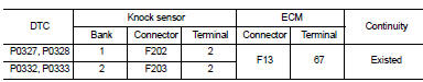
3. Also check harness for short to ground and short to power.
Is the inspection result normal? YES >> GO TO 4.
NO >> GO TO 3.
3.DETECT MALFUNCTIONING PART
Check the following.
• Harness connectors F69, F201
• Harness for open or short between knock sensor and ECM
>> Repair open circuit, short to ground or short to power in harness or connectors.
4.CHECK KNOCK SENSOR INPUT SIGNAL CIRCUIT FOR OPEN AND SHORT
1. Check the continuity between knock sensor harness connector and ECM harness connector.
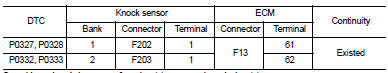
2. Also check harness for short to ground and short to power.
Is the inspection result normal? YES >> GO TO 6.
NO >> GO TO 5.
5.DETECT MALFUNCTIONING PART
Check the following.
• Harness connectors F69, F201
• Harness for open or short between knock sensor and ECM
>> Repair open circuit, short to ground or short to power in harness or connectors.
6.CHECK KNOCK SENSOR
Refer to EC-1290, "Component Inspection".
Is the inspection result normal? YES >> GO TO 7.
NO >> Replace malfunctioning knock sensor.
7.CHECK INTERMITTENT INCIDENT
Refer to GI-42, "Intermittent Incident".
>> INSPECTION END
Component Inspection
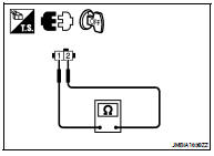
1.CHECK KNOCK SENSOR
1. Turn ignition switch OFF.
2. Disconnect knock sensor harness connector.
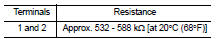
3. Check resistance between knock sensor terminal as per the following.
NOTE: It is necessary to use an ohmmeter which can measure more than 10 MΩ.
CAUTION: Never use any knock sensors that have been dropped or physically damaged. Use only new ones.
Is the inspection result normal? YES >> INSPECTION END
NO >> Replace malfunctioning knock sensor.
 P0300, P0301, P0302, P0303, P0304, P0305, P0306 Misfire
 P0335 CKP sensor (POS)