Nissan Altima (L32) 2007-2012 Service Manual: P0451 evap control system pressure sensor
Description
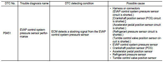
The EVAP control system pressure sensor detects pressure in the purge line. The sensor output voltage to the ECM increases as pressure increases.
DTC Logic
DTC DETECTION LOGIC
DTC CONFIRMATION PROCEDURE
1.PRECONDITIONING
If DTC Confirmation Procedure has been previously conducted, always turn ignition switch OFF and wait at least 10 seconds before conducting the next test.
>> GO TO 2.
2.PERFORM DTC CONFIRMATION PROCEDURE
1. Turn ignition switch OFF and wait at least 10 seconds.
2. Start engine and wait at least 40 seconds.
NOTE: Do not depress accelerator pedal even slightly.
3. Check 1st trip DTC.
Is 1st trip DTC detected? YES >> Go to EC-316, "Diagnosis Procedure".
NO >> INSPECTION END
Diagnosis Procedure
1.CHECK GROUND CONNECTION
1. Turn ignition switch OFF.
2. Check ground connection E9. Refer to Ground Inspection in GI-45, "Circuit Inspection".
Is the inspection result normal? YES >> GO TO 2.
NO >> Repair or replace ground connection.
2.CHECK EVAP CONTROL SYSTEM PRESSURE SENSOR CONNECTOR FOR WATER
1. Disconnect EVAP control system pressure sensor harness connector.
2. Check sensor harness connector for water.
Water should not exist.
Is the inspection result normal? YES >> GO TO 3.
NO >> Repair or replace harness connector.
3.CHECK EVAP CONTROL SYSTEM PRESSURE SENSOR POWER SUPPLY CIRCUIT
1. Turn ignition switch ON.
2. Check the voltage between EVAP control system pressure sensor harness connector and ground.
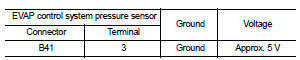
Is the inspection result normal? YES >> GO TO 8.
NO >> GO TO 4.
4.CHECK SENSOR POWER SUPPLY CIRCUITS
Check harness for short to power and short to ground, between the following terminals.
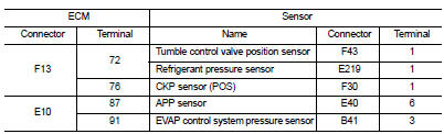
Is the inspection result normal? YES >> GO TO 5.
NO >> Repair short to ground or short to power in harness or connectors.
5.CHECK COMPONENTS
Check the following.
• Crankshaft position sensor (POS) (Refer to EC-281, "Component Inspection".) • Refrigerant pressure sensor (Refer to EC-482, "Diagnosis Procedure".) • Tumble control valve position sensor (Refer to EC-410, "Diagnosis Procedure".) Is the inspection result normal? YES >> GO TO 6.
NO >> Replace malfunctioning component.
6.CHECK APP SENSOR
Refer to EC-429, "Component Inspection".
Is the inspection result normal? YES >> GO TO 9.
NO >> GO TO 7.
7.REPLACE ACCELERATOR PEDAL ASSEMBLY
1. Replace accelerator pedal assembly 2. Go to EC-29, "ACCELERATOR PEDAL RELEASED POSITION LEARNING : Special Repair Requirement".
>> INSPECTION END
8.CHECK EVAP CONTROL SYSTEM PRESSURE SENSOR
Refer to EC-318, "Component Inspection".
Is the inspection result normal? YES >> GO TO 9.
NO >> Replace EVAP control system pressure sensor.
9.CHECK INTERMITTENT INCIDENT
Refer to GI-42, "Intermittent Incident".
>> INSPECTION END
Component Inspection
1.CHECK EVAP CONTROL SYSTEM PRESSURE SENSOR
1. Turn ignition switch OFF.
2. Remove EVAP control system pressure sensor with its harness connector connected from EVAP canister.
Always replace O-ring with a new one.
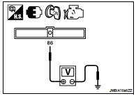
3. Install a vacuum pump to EVAP control system pressure sensor.
4. Turn ignition switch ON and check output voltage between ECM harness connector and ground under the following conditions.
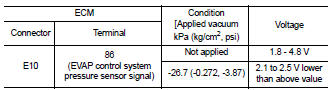
CAUTION: • Always calibrate the vacuum pump gauge when using it.
• Do not apply below -93.3 kPa (-0.952 kg/cm2, -13.53 psi) or pressure over 101.3 kPa (1.033 kg/ cm2, 14.69 psi).
Is the inspection result normal? YES >> INSPECTION END
NO >> Replace EVAP control system pressure sensor
 P0448 evap canister vent control
valve
P0448 evap canister vent control
valve P0452 evap control system pressure
sensor
P0452 evap control system pressure
sensor