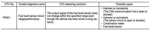
Nissan Altima (L32) 2007-2012 Service Manual: P0461 fuel level sensor
Description
The fuel level sensor is mounted in the fuel level sensor unit.
The sensor detects a fuel level in the fuel tank and transmits a signal to the combination meter. The combination meter sends the fuel level sensor signal to the ECM through CAN communication line.
It consists of two parts, one is mechanical float and the other is variable resistor. Fuel level sensor output voltage changes depending on the movement of the fuel mechanical float.
DTC Logic
DTC DETECTION LOGIC
NOTE: • If DTC P0461 is displayed with DTC UXXXX, first perform the trouble diagnosis for DTC UXXXX.
• If DTC P0461 is displayed with DTC P0607, first perform the trouble diagnosis for DTC P0607. Refer to EC-866, "DTC Logic".
Driving long distances naturally affect fuel gauge level.
This diagnosis detects the fuel gauge malfunction of the gauge not moving even after a long distance has been driven.
DTC CONFIRMATION PROCEDURE
1.PERFORM COMPONENT FUNCTION CHECK
Perform component function check. Refer to EC-849, "Component Function Check".
Use component function check to check the overall function of the fuel level sensor function. During this check, a 1st trip DTC might not be confirmed.
Is the inspection result normal? YES >> INSPECTION END
NO >> Go to EC-850, "Diagnosis Procedure".
Component Function Check
1.PRECONDITIONING
WARNING: When performing following procedure, be sure to observe the handling of the fuel. Refer to FL-10, "Removal and Installation".
TESTING CONDITION: Before starting component function check, preparation of draining fuel and refilling fuel is required. Do you have CONSULT-III? YES >> GO TO 2.
NO >> GO TO 3.
2.PERFORM COMPONENT FUNCTION CHECK

NOTE: Start from step 10, if it is possible to confirm that the fuel cannot be drained by 30 (7-7/8 US gal, 6-5/ 8 Imp gal) in advance.
1. Prepare a fuel container and a spare hose.
2. Release fuel pressure from fuel line, refer to EC-1038, "Inspection".
3. Remove the fuel feed hose on the fuel level sensor unit.
4. Connect a spare fuel hose where the fuel feed hose was removed.
5. Turn ignition switch OFF and wait at least 10 seconds then turn ON.
6. Select “FUEL LEVEL SE” in “DATA MONITOR” mode with CONSULT-III.
7. Check “FUEL LEVEL SE” output voltage and note it.
8. Select “FUEL PUMP RELAY” in “ACTIVE TEST” mode with CONSULT-III.
9. Touch “ON” and drain fuel approximately 30 (7-7/8 US gal, 6-5/8 Imp gal) and stop it.
10. Check “FUEL LEVEL SE” output voltage and note it.
11. Fill fuel into the fuel tank for 30 (7-7/8 US gal, 6-5/8 Imp gal).
12. Check “FUEL LEVEL SE” output voltage and note it.
13. Confirm whether the voltage changes more than 0.03V during step 7 to 10 and 10 to 12.
Is the inspection result normal? YES >> INSPECTION END
NO >> Go to EC-850, "Diagnosis Procedure".
3.PERFORM COMPONENT FUNCTION CHECK

NOTE: Start from step 8, if it is possible to confirm that the fuel cannot be drained by 30 (7-7/8 US gal, 6-5/8 Imp gal) in advance.
1. Prepare a fuel container and a spare hose.
2. Release fuel pressure from fuel line. Refer to EC-1038, "Inspection".
3. Remove the fuel feed hose on the fuel level sensor unit.
4. Connect a spare fuel hose where the fuel feed hose was removed.
5. Turn ignition switch ON.
6. Drain fuel by 30 (7-7/8 US gal, 6-5/8 Imp gal) from the fuel tank using proper equipment.
7. Confirm that the fuel gauge indication varies.
8. Fill fuel into the fuel tank for 30 (7-7/8 US gal, 6-5/8 Imp gal).
9. Confirm that the fuel gauge indication varies.
Is the inspection result normal? YES >> INSPECTION END
NO >> Go to EC-850, "Diagnosis Procedure".
Diagnosis Procedure
1.CHECK COMBINATION METER FUNCTION
Refer to MWI-46, "Component Function Check".
Is the inspection result normal? YES >> GO TO 2.
NO >> Go to MWI-46, "Diagnosis Procedure"
2.CHECK INTERMITTENT INCIDENT
Refer to GI-42, "Intermittent Incident".
>> INSPECTION END
 P0460 fuel level sensor
 P0462, p0463 fuel level sensor