Nissan Altima (L32) 2007-2012 Service Manual: P0500 VSS
Description
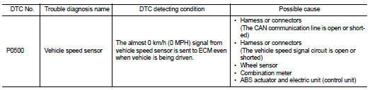
The vehicle speed signal is sent to the combination meter from the “ABS actuator and electric unit (control unit)” by CAN communication line. The combination meter then sends a signal to the ECM by CAN communication line.
DTC Logic
DTC DETECTION LOGIC
NOTE: • If DTC P0500 is displayed with DTC UXXXX, first perform the trouble diagnosis for DTC UXXXX.
• If DTC P0500 is displayed with DTC P0607, first perform the trouble diagnosis for DTC P0607. Refer to EC-361, "DTC Logic".
DTC CONFIRMATION PROCEDURE
1.INSPECTION START
Do you have CONSULT-III? Do you have CONSULT-III? YES >> GO TO 2.
NO >> GO TO 5.
2.PRECONDITIONING
If DTC Confirmation Procedure has been previously conducted, always turn ignition switch OFF and wait at least 10 seconds before conducting the next test.
>> GO TO 3.
3.CHECK VEHICLE SPEED SIGNAL
NOTE: This procedure may be conducted with the drive wheels lifted in the shop or by driving the vehicle. If a road test is expected to be easier, it is unnecessary to lift the vehicle.

1. Start engine.
2. Read “VHCL SPEED SE” in “DATA MONITOR” mode with CONSULT-III. The vehicle speed on CONSULT- III should exceed 10 km/h (6 mph) when rotating wheels with suitable gear position.
Is the inspection result normal? YES >> GO TO 2.
NO >> Go to EC-349, "Diagnosis Procedure".
4.PERFORM DTC CONFIRMATION PROCEDURE
1. Select “DATA MONITOR” mode with CONSULT-III.
2. Warm engine up to normal operating temperature.
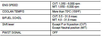
3. Maintain the following conditions for at least 50 consecutive seconds.
CAUTION: Always drive vehicle at a safe speed.
4. Check 1st trip DTC.
Is 1st trip DTC detected? YES >> Go to EC-349, "Diagnosis Procedure".
NO >> INSPECTION END
5.PERFORM COMPONENT FUNCTION CHECK
Perform component function check. Refer to EC-349, "Component Function Check".
Use component function check to check the overall function of the vehicle speed signal circuit. During this check, a 1st trip DTC might not be confirmed.
Is the inspection result normal? YES >> INSPECTION END
NO >> Go to EC-349, "Diagnosis Procedure".
Component Function Check
1.PERFORM COMPONENT FUNCTION CHECK

1. Lift up drive wheels.
2. Start engine.
3. Read vehicle speed signal in Service $01 with GST.
The vehicle speed signal on GST should be able to exceed 10 km/h (6 MPH) when rotating wheels with suitable gear position.
Is the inspection result normal? YES >> INSPECTION END
NO >> Go to EC-349, "Diagnosis Procedure".
Diagnosis Procedure
1.CHECK DTC WITH “ABS ACTUATOR AND ELECTRIC UNIT (CONTROL UNIT)”
Refer to BRC-12, "CONSULT-III Function (ABS)".
Is the inspection result normal? YES >> GO TO 2.
NO >> Repair or replace.
2.CHECK COMBINATION METER
Refer to MWI-38, "CONSULT-III Function (METER/M&A)".
>> INSPECTION END
 P0462, P0463 fuel level sensor
 P0506 ISC System