Nissan Altima (L32) 2007-2012 Service Manual: P0603 ECM Power supply
Description
Battery voltage is supplied to the ECM even when the ignition switch is turned OFF for the ECM memory function of the DTC memory, the air-fuel ratio feedback compensation value memory, the idle air volume learning value memory, etc.
DTC Logic
DTC DETECTION LOGIC
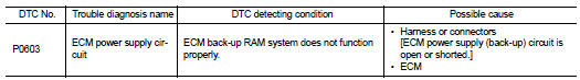
DTC CONFIRMATION PROCEDURE
1.PRECONDITIONING
If DTC Confirmation Procedure has been previously conducted, always turn ignition switch OFF and wait at least 10 seconds before conducting the next test.
>> GO TO 2.
2.PERFORM DTC CONFIRMATION PROCEDURE
1. Turn ignition switch ON and wait at least 1 second.
2. Start engine and let it idle for 1 second.
3. Turn ignition switch OFF, wait at least 10 seconds, and then turn ON.
4. Repeat steps 2 and 3 for four times.
5. Check 1st trip DTC.
Is 1st trip DTC detected? YES >> Go to EC-357, "Diagnosis Procedure".
NO >> INSPECTION END
Diagnosis Procedure
1.CHECK ECM POWER SUPPLY
1. Turn ignition switch OFF.
2. Disconnect ECM harness connector.
3. Check the voltage between ECM harness connector and ground.

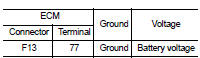
Is the inspection result normal? YES >> GO TO 3.
NO >> GO TO 2.
2.DETECT MALFUNCTIONING PART
Check the following.
• 15A fuse (No. 42) • IPDM E/R harness connector F10
• Harness for open or short between ECM and battery
>> Repair or replace harness or connectors.
3.CHECK INTERMITTENT INCIDENT
Refer to GI-42, "Intermittent Incident".
Is the inspection result normal? YES >> GO TO 4.
NO >> Repair or replace harness or connectors.
4.PERFORM DTC CONFIRMATION PROCEDURE

1. Turn ignition switch ON.
2. Select “SELF-DIAG RESULTS” mode with CONSULT-III.
3. Touch “ERASE”.
4. Perform DTC CONFIRMATION PROCEDURE.
See EC-357, "DTC Logic".

1. Turn ignition switch ON.
2. Select Service $04 with GST.
3. Perform DTC CONFIRMATION PROCEDURE.
See EC-357, "DTC Logic".
Is the 1st trip DTC P0603 displayed again? YES >> GO TO 5.
NO >> INSPECTION END
5.REPLACE ECM
1. Replace ECM.
2. Go to EC-27, "ADDITIONAL SERVICE WHEN REPLACING CONTROL UNIT : Special Repair Requirement".
>> INSPECTION END
 P0550 PSP Sensor
 P0605 ECM