Nissan Altima (L32) 2007-2012 Service Manual: P0615 start signal
Description
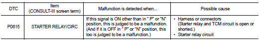
• TCM controls starter relay in IPDM E/R.
• TCM switches starter relay ON at “P” or “N” position and allows to crank engine.
• Then it prohibits cranking other than at “P” or “N” position.
DTC Logic
DTC DETECTION LOGIC
DTC CONFIRMATION PROCEDURE
CAUTION: Always drive vehicle at a safe speed.
Always drive vehicle at a safe speed.
NOTE: If “DTC CONFIRMATION PROCEDURE” has been previously performed, always turn ignition switch OFF.
Then wait at least 10 seconds before performing the next test.
1.CHECK DTC DETECTION

1. Turn ignition switch ON.
2. Perform “SELF-DIAG RESULTS” mode for “TRANSMISSION”.
Is “P0615 STARTER RELAY/CIRC” detected? YES >> Go to TM-124, "Diagnosis Procedure".
NO >> Check intermittent incident. Refer to GI-42, "Intermittent Incident".
Diagnosis Procedure
1.CHECK STARTER RELAY SIGNAL
1. Turn ignition switch OFF.
2. Disconnect TCM harness connector and IPDM E/R harness connector F10.
3. Turn ignition switch ON.
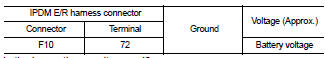
4. Check voltage between IPDM E/R harness connector F10 terminal 72 and ground.
Is the inspection result normal? YES >> Check starter relay and starter control relay. Refer to PCS-14, "Diagnosis Description".
NO >> GO TO 2.
2.CHECK HARNESS BETWEEN TCM AND IPDM E/R (PART 1)
1. Turn ignition switch OFF.
2. Check continuity between TCM harness connector F16 (A) terminal 20 and IPDM E/R harness connector F10 (B) terminal 72.
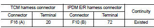
Is the inspection result normal? YES >> GO TO 3.
NO >> Repair or replace damaged parts.
3.CHECK HARNESS BETWEEN TCM AND IPDM E/R 2 (PART 2)
Check continuity between TCM harness connector F16 terminal 20 and ground.
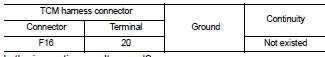
Is the inspection result normal? YES >> GO TO 4.
NO >> Repair or replace damaged parts.
4.DETECT MALFUNCTIONING ITEMS
Check TCM connector pin terminals for damage or loose connection with harness connector.
Is the inspection result normal? YES >> Replace TCM. Refer to TM-254, "Exploded View".
NO >> Repair or replace damaged parts.
 U1000 CAn comm circuit
 P0703 stop lamp switch