Nissan Altima (L32) 2007-2012 Service Manual: P1705 throttle position sensor
Description
Electric throttle control actuator consists of throttle control motor, accelerator pedal position sensor, throttle position sensor etc. The actuator sends a signal to the ECM, and ECM sends the signal to TCM with CAN communication.
DTC Logic
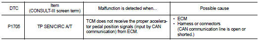
DTC DETECTION LOGIC
DTC CONFIRMATION PROCEDURE
NOTE: If “DTC CONFIRMATION PROCEDURE” has been previously performed, always turn ignition switch OFF.
Then wait at least 10 seconds before performing the next test.
1.CHECK DTC DETECTION

1. Turn ignition switch ON.
2. Depress accelerator pedal fully and release it, then wait for 5 seconds.
3. Perform “SELF-DIAG RESULTS” mode for “TRANSMISSION”.
Is “P1705 TP SEN/CIRC A/T” detected? YES >> Go to TM-352, "Diagnosis Procedure".
NO >> Check intermittent incident. Refer to GI-42, "Intermittent Incident".
Diagnosis Procedure
1.CHECK DTC WITH ECM

1. Turn ignition switch ON.
2. Perform “SELF-DIAG RESULTS” mode for “ENGINE”.
Is the inspection result normal? YES >> GO TO 2.
NO >> Check DTC Detected Item. Refer to EC-527, "DTC Index" (for california), EC-1015, "DTC Index" (except for california).
2.CHECK DTC WITH TCM

Perform “SELF-DIAG RESULTS” mode for “TRANSMISSION”.
Is “P1705 TP SEN/CIRC A/T” detected? YES >> Replace TCM. Refer to TM-430, "Exploded View".
NO >> GO TO 3.
3.DETECT MALFUNCTIONING ITEMS
Check TCM connector pin terminals for damage or loose connection with harness connector.
Is the inspection result normal? YES >> Replace TCM. Refer to TM-430, "Exploded View".
NO >> Repair or replace damaged parts.
 P1701 transmission control module (power supply)
 P1722 estm vehicle speed signal