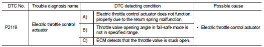
Nissan Altima (L32) 2007-2012 Service Manual: P2119 Electric throttle control actuator
Description
Electric throttle control actuator consists of throttle control motor, throttle position sensor, etc.
The throttle control motor is operated by the ECM and it opens and closes the throttle valve.
The throttle position sensor detects the throttle valve position, and the opening and closing speed of the throttle valve and sends the voltage signals to the ECM. The ECM judges the current opening angle of the throttle valve from these signals and opens/closes the throttle valve in response to driving conditions via the throttle control motor.
DTC Logic
DTC DETECTION LOGIC
DTC CONFIRMATION PROCEDURE
1.PRECONDITIONING
If DTC Confirmation Procedure has been previously conducted, always perform the following before conducting the next test.
1. Turn ignition switch OFF and wait at least 10 seconds.
2. Turn ignition switch ON.
3. Turn ignition switch OFF and wait at least 10 seconds.
>> GO TO 2.
2.PERFORM DTC CONFIRMATION PROCEDURE FOR MALFUNCTION A AND B
1. Turn ignition switch ON and wait at least 1 second.
2. Shift selector lever position to D (CVT) or 1st position (M/T) and wait at least 3 seconds.
3. Shift selector lever position to P (CVT) or neutral position (M/T).
4. Turn ignition switch OFF and wait at least 10 seconds.
5. Turn ignition switch ON and wait at least 1 second.
6. Shift selector lever position to D (CVT) or 1st position (M/T) and wait at least 3 seconds.
7. Shift selector lever position to P (CVT) or neutral position (M/T).
8. Turn ignition switch OFF, wait at least 10 seconds, and then turn ON.
9. Check DTC.
Is DTC detected? YES >> Go to EC-1447, "Diagnosis Procedure".
NO >> GO TO 3.
3.PERFORM DTC CONFIRMATION PROCEDURE FOR MALFUNCTION C
1. Turn ignition switch ON and wait at least 1 second.
2. Shift selector lever position to D (CVT) or 1st position (M/T) and wait at least 3 seconds.
3. Shift selector lever position to N, P (CVT) neutral position (M/T).
4. Start engine and let it idle for 3 seconds.
5. Check DTC.
Is DTC detected? YES >> Go to EC-1447, "Diagnosis Procedure".
NO >> INSPECTION END
Diagnosis Procedure
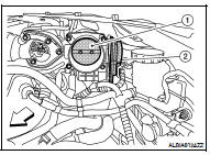
1.CHECK ELECTRIC THROTTLE CONTROL ACTUATOR VISUALLY
1. Turn ignition switch OFF.
2. Remove the intake air duct.
3. Check if foreign matter is caught between the throttle valve (1) and the housing.
- Electric throttle control actuator (2)

Is the inspection result normal? YES >> GO TO 2.
NO >> Remove the foreign matter and clean the electric throttle control actuator inside.
2.REPLACE ELECTRIC THROTTLE CONTROL ACTUATOR
1. Replace electric throttle control actuator.
2. Go to EC-1393, "Special Repair Requirement".
>> INSPECTION END
Special Repair Requirement
1.PERFORM THROTTLE VALVE CLOSED POSITION LEARNING
Refer to EC-1053, "THROTTLE VALVE CLOSED POSITION LEARNING : Special Repair Requirement" >> GO TO 2.
2.PERFORM IDLE AIR VOLUME LEARNING
Refer to EC-1053, "IDLE AIR VOLUME LEARNING : Special Repair Requirement" >> END
 P2118 Throttle control motor
 P2122, P2123 APP Sensor