Nissan Altima (L32) 2007-2012 Service Manual: Power distribution system
System Description
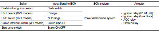
INPUT/OUTPUT SIGNAL CHART
SYSTEM DESCRIPTION
• PDS (POWER DISTRIBUTION SYSTEM) is the system that BCM controls with the operation of the pushbutton ignition switch and performs the power distribution to each power circuit. This system is used instead of the mechanical power supply changing mechanism with the operation of the conventional key cylinder.
• The push-button ignition switch can be operated when Intelligent Key is in the following condition. Refer to Engine Start Function for details.
- Intelligent Key is in the detection area of the interior antenna
- Insert Intelligent Key in to the key slot
• The push-button ignition switch operation is input to BCM as a signal. BCM changes the power supply position according to the status and operates the following relays to supply power to each power circuit.
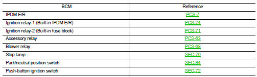
- Ignition relay (inside IPDM E/R)
- Ignition relay (inside fuse block)
- ACC relay
- Blower fan relay
NOTE: The engine switch operation changes due to the conditions of brake pedal, CVT selector lever and vehicle speed.
• The power supply position can be confirmed with the lighting of the indicators near the push-button ignition switch.
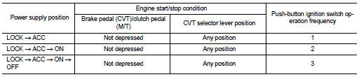
PUSH-BUTTON IGNITION SWITCH OPERATION PROCEDURE
The power supply position changing operation can be performed with the following operation.
NOTE: • When an Intelligent Key is within the detection area of inside key antenna and when it is inserted in to the key slot, it is equivalent to the operations below.
• When starting the engine, the BCM monitors under the engine start conditions, - Brake pedal operating condition (CVT models) - CVT selector lever position (CVT models) - Clutch pedal operating condition (M/T models) - Vehicle speed
• Unless each start condition is fulfilled, the engine will not respond regardless of how many times the engine switch is pressed. At that time, illumination repeats the position in the order of LOCK→ACC→ON→OFF.
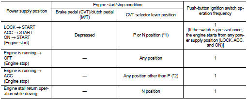
*1: When the CVT selector lever position is N position, the engine start condition is different according to the vehicle speed.
• At vehicle speed of 4 km/h or less, the engine can start only when the brake pedal is depressed.
• At vehicle speed of 4 km/h or more, the engine can start even if the brake pedal is not depressed. (It is the same as “Engine stall return operation while driving”.) *2: When the CVT selector lever position is in any position other than P position and when the vehicle speed is 5 km/h or more, the engine stop condition is different.
• Press and hold the push-button ignition switch for 2 seconds or more. (When the push-button ignition switch is pressed for too short a time, the operation may be invalid, so properly press and hold to prevent the incorrect operation.) • Press the push-button ignition switch 3 times or more within 1.5 seconds. (Emergency stop operation)
Component Parts Location

1. BCM M16, M17, M18, M19, M21 (view with instrument panel removed)
2. IPDM E/R E16, E17, E18 (contains IGN relay-1)
3. A. Fuse block (J/B) M3, M4, M5, E6
B. IGN relay-2
C. ACC relay
D. Blower motor relay
4. Push-button ignition switch M38

Component Description
 Function diagnosis
 Diagnosis system (BCM)