Nissan Altima (L32) 2007-2012 Service Manual: Power supply and ground circuit
SUNROOF MOTOR ASSEMBLY
Description
• BCM supplies power.
• CPU is integrated in sunroof motor assembly.
• Tilts up/down & slides open/close by sunroof switch operation.
• In order to close sunroof lid certainly with the signal from combination meter at the time of high speed run, the sunroof motor torque at the time of tilt-down operation is controlled.
Component Function Check
1. CHECK SUNROOF MOTOR FUNCTION
Do tilt up/down & slide open/close functions operate normally with sunroof switch? Is the inspection result normal? YES >> Sunroof motor assembly is OK.
NO >> Refer to RF-12, "SUNROOF MOTOR ASSEMBLY : Diagnosis Procedure".
Diagnosis Procedure
SUNROOF MOTOR ASSEMBLY
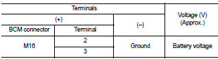
1. CHECK POWER SUPPLY CIRCUIT
1. Turn ignition switch OFF.
2. Disconnect sunroof motor assembly.
3. Turn ignition switch ON.
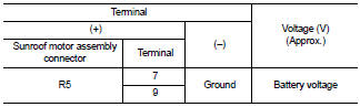
4. Check voltage between sunroof motor assembly connector and ground.
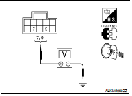
Is the measurement value within the specification? YES >> GO TO 2
NO >> GO TO 3
2. CHECK GROUND CIRCUIT
1. Turn ignition switch OFF.
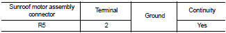
2. Check continuity between sunroof motor assembly connector and ground.
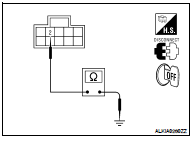
Is the inspection result normal? YES >> GO TO 5
NO >> Repair or replace harness.
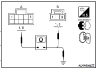
3. CHECK SUNROOF MOTOR CIRCUIT
1. Turn ignition switch OFF.
2. Disconnect BCM.
3. Check continuity between BCM connector (A) and sunroof motor assembly connector (B).
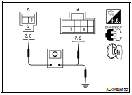
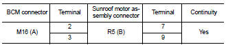
4. Check continuity between BCM connector (A) and ground.
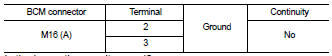
Is the inspection result normal? YES >> GO TO 4
NO >> Repair or replace harness.
4. CHECK BCM OUTPUT SIGNAL
1. Connect BCM.
2. Turn ignition switch ON.
3. Check voltage between BCM connector and ground.
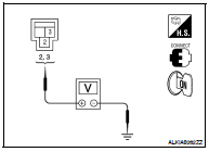
Is the measurement value within the specification? YES >> Check condition of harness and connector.
NO >> Replace BCM. Refer to BCS-96, "Removal and Installation".
5. CHECK SUNROOF SWITCH INPUT SIGNAL
1. Connect sunroof motor assembly.
2. Turn ignition switch ON.
3. Check voltage between sunroof motor assembly connector and ground.
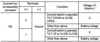
Is the measurement value within the specification? YES >> GO TO 8
NO >> GO TO 6
6. CHECK SUNROOF SWITCH CIRCUIT
1. Turn ignition switch OFF.
2. Disconnect sunroof motor assembly and sunroof switch.
3. Check continuity between sunroof motor assembly connector (A) and sunroof switch connector (B).
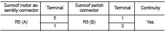
4. Check continuity between sunroof motor assembly connector (A) and ground.
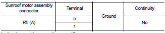
Is the inspection result normal? YES >> GO TO 7
NO >> Repair or replace harness.
7. CHECK SUNROOF SWITCH GROUND CIRCUIT
1. Connect sunroof motor assembly.
2. Check continuity between sunroof switch connector and ground.
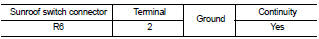
Is the inspection result normal? YES >> Refer to RF-15, "SUNROOF MOTOR ASSEMBLY : Component Inspection".
NO >> Repair or replace harness.
8. CHECK COMBINATION METER SIGNAL
1. Connect sunroof motor assembly.
2. Turn ignition switch ON.
3. Check signal between sunroof motor assembly connector and ground with oscilloscope.
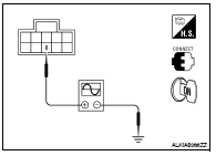
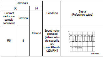
Is the inspection result normal?
YES >> Replace sunroof motor assembly. Refer to RF-95, "Removal and Installation". After that, refer to RF-6, "ADDITIONAL SERVICE WHEN REPLACING CONTROL UNIT : Special Repair Requirement".
NO >> GO TO 9
9.CHECK COMBINATION METER CIRCUIT
1. Turn ignition switch OFF.
2. Disconnect combination meter.
3. Check continuity between combination meter connector (A) and sunroof motor assembly connector (B).
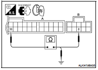
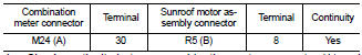
4. Check continuity between combination meter connector (A) and ground.
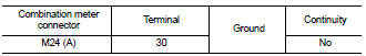
Is the inspection result normal? YES >> Replace combination meter. Refer to MWI-176, "Removal and Installation".
NO >> Repair or replace harness.
Component Inspection
SUNROOF SWITCH
1. CHECK SUNROOF SWITCH
1. Turn ignition switch OFF.
2. Disconnect sunroof switch.
3. Check continuity between sunroof switch terminals.
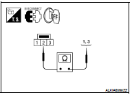
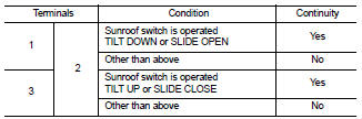
Is the inspection result normal? YES >> Sunroof switch is OK.
NO >> Replace sunroof switch (map lamp assembly). Refer to INL-121, "Removal and Installation".
Special Repair Requirement
1. PERFORM INITIALIZATION PROCEDURE
Perform initialization procedure.
Refer to RF-6, "ADDITIONAL SERVICE WHEN REPLACING CONTROL UNIT : Special Repair Requirement".
>> GO TO 2
2. CHECK ANTI-PINCH OPERATION
Check anti-pinch operation.
Refer to RF-6, "ADDITIONAL SERVICE WHEN REPLACING CONTROL UNIT : Special Repair Requirement".
Is the inspection result normal? YES >> Inspection End.
NO >> Check fitting adjustment. Refer to RF-91, "Inspection".
 Component diagnosis
 Door switch