Nissan Altima (L32) 2007-2012 Service Manual: Power supply and ground circuit
Diagnosis Procedure
1.INSPECTION START
Start engine.
Is engine running? YES >> GO TO 8.
NO >> GO TO 2.
2.CHECK ECM POWER SUPPLY CIRCUIT-I
1. Turn ignition switch OFF and then ON.
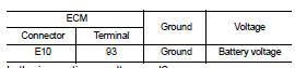
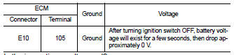
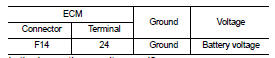
2. Check the voltage between ECM harness connector and ground.
Is the inspection result normal? YES >> GO TO 4.
NO >> GO TO 3.
3.DETECT MALFUNCTIONING PART
Check the following.
• IPDM E/R harness connector E18 • 10A fuse (No. 35) • Harness for open or short between ECM and fuse >> Repair open circuit or short to ground or short to power in harness or connectors.
4.CHECK GROUND CONNECTION-I
1. Turn ignition switch OFF.
2. Check ground connection E9. Refer to Ground Inspection in GI-45, "Circuit Inspection".
Is the inspection result normal? YES >> GO TO 5.
NO >> Repair or replace ground connection.
5.CHECK ECM GROUND CIRCUIT FOR OPEN AND SHORT-I
1. Disconnect ECM harness connectors.
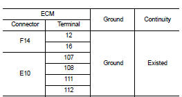
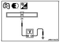
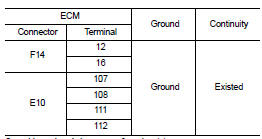
2. Check the continuity between ECM harness connector and ground.
3. Also check harness for short to power.
Is the inspection result normal? YES >> GO TO 7.
NO >> GO TO 6.
6.DETECT MALFUNCTIONING PART
Check the following.
• Harness connectors F2, E11
• Harness for open or short between ECM and ground
>> Repair open circuit or short to power in harness or connectors.
7.CHECK ECM POWER SUPPLY CIRCUIT-II
1. Reconnect ECM harness connectors.
2. Turn ignition switch ON.
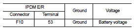
3. Check the voltage between IPDM E/R harness connector and ground.
Is the inspection result normal? YES >> Go to EC-470, "Diagnosis Procedure".
NO >> GO TO 8.
8.CHECK ECM POWER SUPPLY CIRCUIT-III
1. Turn ignition switch OFF and wait at least 10 seconds.
2. Check the voltage between ECM harness connector and ground.
Is the inspection result normal? YES >> GO TO 14.
NO-1 >> Battery voltage does not exist: GO TO 9.
NO-2 >> Battery voltage exists for more than a few seconds: GO TO 12.
9.CHECK ECM POWER SUPPLY CIRCUIT-IV
1. Turn ignition switch OFF and wait at least 10 seconds.
2. Check the voltage between ECM harness connector and ground.
Is the inspection result normal? YES >> GO TO 10.
NO >> GO TO 12.
10.CHECK ECM POWER SUPPLY CIRCUIT-V
1. Disconnect ECM harness connector.
2. Disconnect IPDM E/R harness connector E18.
3. Check the continuity between ECM harness connector and IPDM E/R harness connector.
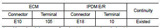
4. Also check harness for short to ground and short to power.
Is the inspection result normal? YES >> GO TO 17.
NO >> GO TO 11.
11.DETECT MALFUNCTIONING PART
Check the following.
• Junction block connectors E44, E45
• Harness for open or short between ECM and IPDM E/R
>> Repair open circuit or short to ground or short to power in harness or connectors.
12.CHECK ECM POWER SUPPLY CIRCUIT-VI
1. Disconnect ECM harness connector.
2. Disconnect IPDM E/R harness connector F10.
3. Check the continuity between ECM harness connector and IPDM E/R harness connector.
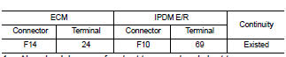
4. Also check harness for short to ground and short to power.
Is the inspection result normal? YES >> GO TO 13.
NO >> Repair open circuit or short to ground or short power in harness or connectors.
13.CHECK 15A FUSE
1. Disconnect 15A fuse (No. 42) from IPDM E/R.
2. Check 15A fuse.
Is the inspection result normal? YES >> GO TO 17.
NO >> Replace 15A fuse.
14.CHECK GROUND CONNECTION-II
1. Turn ignition switch OFF.
2. Check ground connection E9. Refer to Ground Inspection in GI-45, "Circuit Inspection".
Is the inspection result normal? YES >> GO TO 15.
NO >> Repair or replace ground connection.
15.CHECK ECM GROUND CIRCUIT FOR OPEN AND SHORT-II
1. Disconnect ECM harness connector.
2. Check the continuity between ECM harness connector and ground.
3. Also check harness for short to power.
Is the inspection result normal? YES >> GO TO 17.
NO >> GO TO 16.
16.DETECT MALFUNCTIONING PART
Check the following.
• Harness or connectors F2, E11
• Harness for open or short between ECM and ground
>> Repair open circuit or short to power in harness or connectors.
17.CHECK INTERMITTENT INCIDENT
Refer to GI-42, "Intermittent Incident".
Is the inspection result normal? YES >> Replace IPDM E/R.
NO >> Repair open circuit or short to power in harness or connectors.
 Trouble diagnosis - specification
value
Trouble diagnosis - specification
value U0101 Can comm circuit