Nissan Altima (L32) 2007-2012 Service Manual: Precaution
Precaution for Supplemental Restraint System (SRS) "AIR BAG" and "SEAT BELT PRE-TENSIONER"
The Supplemental Restraint System such as “AIR BAG” and “SEAT BELT PRE-TENSIONER”, used along with a front seat belt, helps to reduce the risk or severity of injury to the driver and front passenger for certain types of collision. This system includes seat belt switch inputs and dual stage front air bag modules. The SRS system uses the seat belt switches to determine the front air bag deployment, and may only deploy one front air bag, depending on the severity of a collision and whether the front occupants are belted or unbelted.
Information necessary to service the system safely is included in the SR and SB section of this Service Manual.
WARNING: • To avoid rendering the SRS inoperative, which could increase the risk of personal injury or death in the event of a collision which would result in air bag inflation, all maintenance must be performed by an authorized NISSAN/INFINITI dealer.
• Improper maintenance, including incorrect removal and installation of the SRS, can lead to personal injury caused by unintentional activation of the system. For removal of Spiral Cable and Air Bag Module, see the SR section.
• Do not use electrical test equipment on any circuit related to the SRS unless instructed to in this Service Manual. SRS wiring harnesses can be identified by yellow and/or orange harnesses or harness connectors.
Necessary for Steering Wheel Rotation After Battery Disconnect
NOTE: • Before removing and installing any control units, first turn the push-button ignition switch to the LOCK position, then disconnect both battery cables.
• After finishing work, confirm that all control unit connectors are connected properly, then re-connect both battery cables.
• Always use CONSULT-III to perform self-diagnosis as a part of each function inspection after finishing work.
If a DTC is detected, perform trouble diagnosis according to self-diagnosis results.
This vehicle is equipped with a push-button ignition switch and a steering lock unit.
If the battery is disconnected or discharged, the steering wheel will lock and cannot be turned.
If turning the steering wheel is required with the battery disconnected or discharged, follow the procedure below before starting the repair operation.
OPERATION PROCEDURE
1. Connect both battery cables.
NOTE: Supply power using jumper cables if battery is discharged.
2. Carry the Intelligent Key or insert it to the key slot and turn the push-button ignition switch to ACC position.
(At this time, the steering lock will be released.) 3. Disconnect both battery cables. The steering lock will remain released with both battery cables disconnected and the steering wheel can be turned.
4. Perform the necessary repair operation.
5. When the repair work is completed, re-connect both battery cables. With the brake pedal released, turn the push-button ignition switch from ACC position to ON position, then to LOCK position. (The steering wheel will lock when the push-button ignition switch is turned to LOCK position.) 6. Perform self-diagnosis check of all control units using CONSULT-III.
Precaution for Drain Coolant
• Drain coolant when engine is cooled.
Precaution for Disconnecting Fuel Piping
• Before starting work, make sure no fire or spark producing items are in the work area.
• Release fuel pressure before disassembly.
• After disconnecting pipes, plug openings to stop fuel leakage.
Precaution for Removal and Disassembly
• When instructed to use special service tools, use the specified tools. Always be careful to work safely, avoid forceful or uninstructed operations.
• Exercise maximum care to avoid damage to mating or sliding surfaces.
• Cover openings of engine system with tape or the equivalent, if necessary, to seal out foreign materials.
• Mark and arrange disassembly parts in an organized way for easy troubleshooting and assembly.
• When loosening nuts and bolts, as a basic rule, start with the one furthest outside, then the one diagonally opposite, and so on. If the order of loosening is specified, do exactly as specified. Power tools may be used where noted in the step.
Precaution for Inspection, Repair and Replacement
• Before repairing or replacing, thoroughly inspect parts. Inspect new replacement parts in the same way, and replace if necessary.
Precaution for Assembly and Installation
• Use torque wrench to tighten bolts or nuts to specification.
• When tightening nuts and bolts, as a basic rule, equally tighten in several different steps starting with the ones in center, then ones on inside and outside diagonally in this order. If the order of tightening is specified, do exactly as specified.
• Replace with new gasket, packing, oil seal or O-ring.
• Thoroughly wash, clean, and air-blow each part. Carefully check oil or coolant passages for any restriction and blockage.
• Avoid damaging sliding or mating surfaces. Completely remove foreign materials such as cloth lint or dust.
Before assembly, oil sliding surfaces well.
• Release air within route after draining coolant.
• Before starting engine, apply fuel pressure to fuel lines with turning ignition switch ON (with engine stopped).
Then make sure that there are no leaks at fuel line connections.
• After repairing, start engine and increase engine speed to check coolant, fuel, oil, and exhaust systems for leakage.
Parts Requiring Angular Tightening
• Use an angle wrench for the final tightening of the following engine parts: - Cylinder head bolts
- Main bearing cap bolts
- Connecting rod cap nuts
- Crankshaft pulley bolt (No angle wrench is required as the bolt flange is provided with notches for angular tightening)
• Do not use a torque value for final tightening.
• The torque value for these parts are for a preliminary step.
• Ensure thread and seat surfaces are clean and coated with engine oil.
Precaution for Liquid Gasket
REMOVAL OF LIQUID GASKET SEALING
• After removing the bolts and nuts, separate the mating surface and remove the sealant using Tool.
Tool number : KV10111100 (J-37228)
CAUTION: Be careful not to damage the mating surfaces.
• In areas where the cutter is difficult to use, use a plastic hammer to lightly tap (1) the cutter where the RTV Silicone Sealant is applied.
Use a plastic hammer to slide the cutter (2) by tapping on the side.
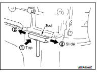
CAUTION:
If for some unavoidable reason a tool such as a flat-bladed screwdriver is used, be careful not to damage the mating surfaces.
LIQUID GASKET APPLICATION PROCEDURE
1. Using a scraper, remove the old Silicone RTV Sealant adhering to the gasket application surface and the mating surface.
• Remove the sealant completely from the groove of the gasket application surface, bolts, and bolt holes.
2. Thoroughly clean the gasket application surface and the mating surface and remove adhering moisture, grease and foreign materials.
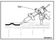
3. Attach the sealant tube to the tube presser.
Use Genuine Silicone RTV Sealant or equivalent. Refer to GI-15, "Recommended Chemical Products and Sealants".
4. Apply the sealant using Tool without breaks to the specified location.
Tube presser WS39930000 ( – )
• If there is a groove for the sealant application, apply the sealant to the groove.
• As for the bolt holes, normally apply the sealant inside the holes. If specified, it should be applied outside the holes. Make sure to read the text of this manual.
• Within five minutes of the sealant application, install the mating component.
• If the sealant protrudes, wipe it off immediately.
• Do not retighten after the installation.
• After 30 minutes or more have passed from the installation, fill the engine with the specified oil and coolant. Refer to MA-12, "Fluids and Lubricants".
CAUTION: Follow all specific instructions in this manual.
 Service data and specifications
(SDS)
Service data and specifications
(SDS) Preparation