Nissan Altima (L32) 2007-2012 Service Manual: Removal and installation
TRANSAXLE ASSEMBLY
Exploded View
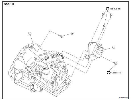
1. Transaxle assembly
2. LH engine mounting bracket
A. Refer to TM-26, "Removal and Installation"
Removal and Installation
CAUTON: If transaxle assembly is removed from the vehicle, always replace CSC (Concentric Slave Cylinder).
Inserted CSC returns to the original position when removing transaxle assembly. Dust on clutch disc sliding parts may damage CSC seal and may cause clutch fluid leakage.
REMOVAL
1. Remove the engine and transaxle as an assembly. Refer to EM-72, "Removal and Installation" (QR25DE), EM-202, "Removal and Installation" (VQ35DE).
CAUTION: Do not depress clutch pedal during removal procedure.
2. Disconnect the electrical connectors from the following: • Back-up lamp switch • Park/neutral position switch 3. Remove the harness from the transaxle.
4. Remove the starter motor. Refer to STR-25, "Removal and Installation" (QR25DE), STR-51, "Removal and Installation" (VQ35DE).
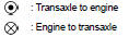
5. Remove the transaxle to engine and engine to transaxle bolts.
6. Separate the transaxle from the engine.
7. If necessary remove the following: • Air breather hose
• Switches
• LH engine mount
• Brackets
INSTALLATION
Installation is in the reverse order of removal.
• If transaxle is removed from the vehicle, always replace CSC. Refer to CL-13, "Removal and Installation".
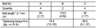
• When installing the transaxle assembly to the engine, install the bolts following the standard below.
CAUTION: When installing transaxle assembly do not bring transaxle input shaft into contact with clutch cover.
- QR25DE engine models
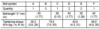
- VQ35DE engine models
• Bleed the air from the clutch hydraulic system. Refer to CL-7, "Air Bleeding Procedure".
• After installation, check oil level, and check for leaks and loose mechanisms. Refer to TM-17, "Inspection".
 Air breather hose
 Disassembly and assembly