Nissan Altima (L32) 2007-2012 Service Manual: Seat belt buckle switch signal circuit
Description
Transmits a seat belt buckle switch signal to the combination meter.
Component Function Check
1. CHECK COMBINATION METER INPUT SIGNAL
Select “DATA MONITOR” for “METER/M&A” and check the “BUCKLE SW” monitor value.
>> Inspection End.
Diagnosis Procedure
1. CHECK COMBINATION METER INPUT SIGNAL
1. Turn ignition switch ON.
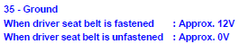
2. Check voltage between combination meter harness connector M24 terminal 35 and ground.
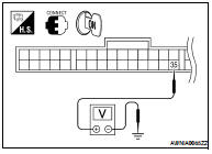
Is the inspection result normal? YES >> Replace combination meter. Refer to MWI-176, "Removal and Installation".
NO >> GO TO 2
2. CHECK SEAT BELT BUCKLE SWITCH CIRCUIT
1. Turn ignition switch OFF.
2. Disconnect combination meter and seat belt buckle switch LH.
3. Check continuity between combination meter harness connector M24 terminal 35 and seat belt buckle switch LH harness connector B202 terminal 1.

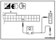
4. Check harness continuity between combination meter harness connector M24 terminal 35 and ground.

Is the inspection result normal? YES >> GO TO 3
NO >> Repair or replace harness.
3. CHECK SEAT BELT BUCKLE SWITCH GROUND CIRCUIT
Check harness continuity between seat belt buckle switch LH harness connector B202 terminal 2 and ground.

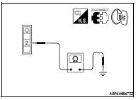
Is the inspection result normal? YES >> Inspection End.
NO >> Repair or replace harness.
Component Inspection
1. CHECK SEAT BELT BUCKLE SWITCH
1. Turn ignition switch OFF.
2. Disconnect the seat belt buckle switch.
3. Check continuity between terminals 1 and 2.
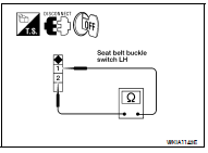
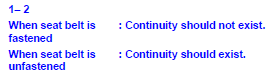
Is the inspection result normal? YES >> Inspection End.
NO >> Replace the seat belt buckle switch LH.
 Meter buzzer circuit
 Warning chime system