Nissan Altima (L32) 2007-2012 Service Manual: Shift lock system
System Diagram
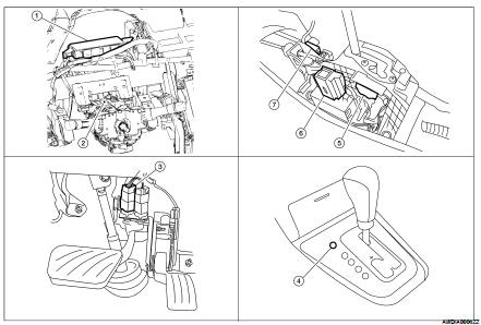
System Description
The selector lever cannot be shifted from “P” position to any other position
unless the ignition switch is in the
ON position and the brake pedal is depressed.
System Diagram
NOTE:
The gear ratio is set for every position separately.
System Description
In order to select the gear ratio which can obtain the driving force in
accordance with driver's ...
Diagnosis Description
DESCRIPTION
The CVT system has two self-diagnostic systems.
The first is the emission-related on board diagnostic system (OBD-II) performed
by the TCM in combination
wit ...
 Shift mechanism
 On board diagnostic (OBD) System