Nissan Altima (L32) 2007-2012 Service Manual: On board diagnostic (OBD) System
Diagnosis Description
DESCRIPTION
The CVT system has two self-diagnostic systems.
The first is the emission-related on board diagnostic system (OBD-II) performed by the TCM in combination with the ECM. The malfunction is indicated by the MIL (malfunction indicator lamp) and is stored as a DTC in the ECM memory, and the TCM memory.
The second is the TCM original self-diagnosis performed by the TCM. The malfunction is stored in the TCM memory. The detected items are overlapped with OBD-II self-diagnostic items. For detail, refer to TM-298, "CONSULT-III Function (TRANSMISSION)".
OBD-II FUNCTION
The ECM provides emission-related on board diagnostic (OBD-II) functions for the CVT system. One function is to receive a signal from the TCM used with OBD-related parts of the CVT system. The signal is sent to the ECM when a malfunction occurs in the corresponding OBD-related part. The other function is to indicate a diagnostic result by means of the MIL (malfunction indicator lamp) on the instrument panel. Sensors, switches and solenoid valves are used as sensing elements.
The MIL automatically illuminates in “One or Two Trip Detection Logic” when a malfunction is sensed in relation to CVT system parts.
ONE OR TWO TRIP DETECTION LOGIC OF OBD-II
One Trip Detection Logic
If a malfunction is sensed during the first test drive, the MIL will illuminate and the malfunction will be stored in the ECM memory as a DTC. The TCM is not provided with such a memory function.
Two Trip Detection Logic
When a malfunction is sensed during the first test drive, it is stored in the ECM memory as a 1st trip DTC (diagnostic trouble code) or 1st trip freeze frame data. At this point, the MIL will not illuminate. — 1st trip If the same malfunction as that experienced during the first test drive is sensed during the second test drive, the MIL will illuminate. — 2nd trip
The “trip” in the “One or Two Trip Detection Logic” means a driving mode in which self-diagnosis is performed during vehicle operation.
OBD-II DIAGNOSTIC TROUBLE CODE (DTC)
How to Read DTC and 1st Trip DTC
DTC and 1st trip DTC can be read by the following methods.
(  with CONSULT-III or
 GST) CONSULT-III or GST (Generic
Scan Tool) Examples: P0705, P0720 etc.
GST) CONSULT-III or GST (Generic
Scan Tool) Examples: P0705, P0720 etc.
These DTC are prescribed by SAE J2012.
(CONSULT-III also displays the malfunctioning component or system.) • 1st trip DTC No. is the same as DTC No.
• Output of the diagnostic trouble code indicates that the indicated circuit has a malfunction. However, in case of the Mode II and GST, they do not indicate whether the malfunction is still occurring or occurred in the past and returned to normal.
CONSULT-III can identify them as shown below, therefore, CONSULT-III (if available) is recommended.
- DTC or 1st trip DTC of a malfunction is displayed in SELF-DIAGNOSTIC RESULTS mode for “ENGINE” with CONSULT-III. Time data indicates how many times the vehicle was driven after the last detection of a DTC.
- If the DTC is being detected currently, the time data will be “0”.
- If a 1st trip DTC is stored in the ECM, the time data will be “1t”.
Freeze Frame Data and 1st Trip Freeze Frame Data
• The ECM has a memory function, which stores the driving condition such as fuel system status, calculated load value, engine coolant temperature, short term fuel trim, long term fuel trim, engine speed and vehicle speed at the moment the ECM detects a malfunction.
Data which are stored in the ECM memory, along with the 1st trip DTC, are called 1st trip freeze frame data, and the data, stored together with the DTC data, are called freeze frame data and displayed on CONSULTIII or GST. The 1st trip freeze frame data can only be displayed on the CONSULT-III screen, not on the GST.
For details, refer to EC-125, "CONSULT-III Function" (for California), EC-654, "CONSULT-III Function" (except for California).
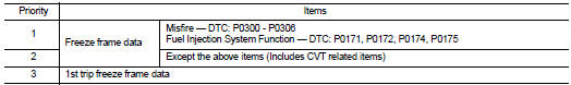
Only one set of freeze frame data (either 1st trip freeze frame data or freeze frame data) can be stored in the ECM. 1st trip freeze frame data is stored in the ECM memory along with the 1st trip DTC. There is no priority for 1st trip freeze frame data, and it is updated each time a different 1st trip DTC is detected. However, once freeze frame data (2nd trip detection/MIL on) is stored in the ECM memory, 1st trip freeze frame data is no longer stored. Remember, only one set of freeze frame data can be stored in the ECM. The ECM has the following priorities to update the data.
Both 1st trip freeze frame data and freeze frame data (along with the DTC) are cleared when the ECM memory is erased.
How to Erase DTC
• The diagnostic trouble code can be erased by CONSULT-III, GST or ECM DIAGNOSTIC TEST MODE as described following.
- If the battery cable is disconnected, the diagnostic trouble code will be lost within 24 hours.
- When you erase the DTC, using CONSULT-III or GST is easier and quicker than switching the mode selector on the ECM.
• The following emission-related diagnostic information is cleared from the ECM memory when erasing DTC related to OBD-II. For details, refer to EC-125, "CONSULT-III Function" (for California), EC-654, "CONSULTIII Function" (except for California).
- Diagnostic trouble codes (DTC) - 1st trip diagnostic trouble codes (1st trip DTC)
- Freeze frame data
- 1st trip freeze frame data
- System readiness test (SRT) codes
- Test values

The emission related diagnostic information in the TCM and ECM can be erased by selecting “ALL Erase” in the “Description” of “FINAL CHECK” mode with CONSULT-III.

1. If the ignition switch stays ON after repair work, be sure to turn ignition switch OFF once. Wait at least 10 seconds and then turn it ON (engine stopped) again.
2. Select Mode 4 with GST (Generic Scan Tool). For details, refer to EC-125, "CONSULT-III Function" (for California), EC-654, "CONSULT-III Function" (except for California).
MALFUNCTION INDICATOR LAMP (MIL)
Description
The MIL is located on the instrument panel.
1. The MIL will light up when the ignition switch is turned ON without the engine running. This is a bulb check.
• If the MIL does not light up, refer to MWI-28, "WARNING LAMPS/INDICATOR LAMPS : System Diagram" (for California), MWI-28, "WARNING LAMPS/INDICATOR LAMPS : System Diagram" (except for California).
2. When the engine is started, the MIL should go off.
If the MIL remains on, the on board diagnostic system has detected an engine system malfunction.
 Shift lock system
 Diagnosis system (TCM)