Nissan Altima (L32) 2007-2012 Service Manual: SRS air bag system
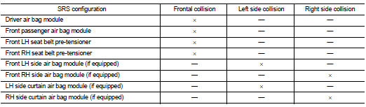
SRS Configuration
The air bag deploys if the air bag diagnosis sensor unit is activated while the ignition switch is in the ON or START position.
The collision modes for which supplemental restraint systems are activated are different among the SRS systems.
For example, the driver air bag module, front passenger air bag module and front seat belt pre-tensioners are activated in a frontal collision but not in a side collision.
SRS configurations for some collision modes are as follows:
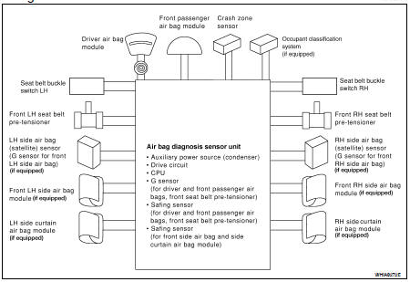
SRS Component Parts Location
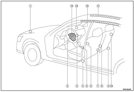
1. Crash zone sensor
2. Spiral cable
3. Front passenger air bag off indicator (if equipped)
4. Front LH seatbelt pre-tensioner LH side air bag (satellite) sensor (if equipped)
5. Air bag diagnosis sensor unit
6. Front LH side air bag module (if equipped)
7. Seat belt buckle switch (LH) Seat belt buckle switch (RH)
8. Occupant classification system control unit and sensor mat (if equipped)
9. Front RH seatbelt pre-tensioner RH side air bag (satellite) sensor (if equipped)
10. Front RH side air bag module (if equipped)
11. RH side curtain air bag module (if equipped)
12. LH side curtain air bag module (if equipped)
13. Front passenger air bag module
14. Driver air bag module
Driver Air Bag Module
The driver air bag module is dual stage and located in the steering wheel assembly. It operates with the SRS system in a frontal collision exceeding a specified level.
Front Passenger Air Bag Module
The front passenger air bag module is located behind the instrument panel assembly. It operates with the SRS system in a frontal collision exceeding a specified level. Refer to SRC-10, "Occupant Classification System (OCS)" for more information.
Front Side Air Bag
Front side air bag modules are built into the front seatback assemblies.
Vehicles with side air bags are equipped with labels as shown.
Side Curtain Air Bag
Side curtain air bag modules are located above the vehicle headlining.
Vehicles with side curtain air bags are equipped with labels as shown.
Front Seat Belt Pre-tensioner with Load Limiter
The seat belt pre-tensioner system with load limiter is installed for both the driver's seat and the front passenger's seat. It operates simultaneously with the SRS air bag system in the event of a frontal collision with an impact exceeding a specified level.
When the frontal collision with an impact exceeding a specified level occurs, seat belt slack resulting from clothing or other factors is immediately taken up by the pre-tensioner. Vehicle passengers are securely restrained.
When passengers in a vehicle are thrown forward in a collision and the restraining force of the seat belt exceeds a specified level, the load limiter permits the specified extension of the seat belt by the twisting of the ELR shaft, and a relaxation of the chest-area seat belt web tension while maintaining force.
Direct-connect SRS Component Connectors
The following SRS components use direct-connect style harness connectors.
• Driver front air bag module
• Passenger front air bag module
• LH side curtain air bag module
• RH side curtain air bag module
• Front LH seat belt pre-tensioner
• Front RH seat belt pre-tensioner
Always pull up to release locking tab prior to removing connector from SRS component.
Always push down to lock locking tab after installing connector to SRS component. When locked, the locking tab is level with the connector housing.
 Function diagnosis
 Occupant classification system