Nissan Altima (L32) 2007-2012 Service Manual: Water control valve
Removal and Installation
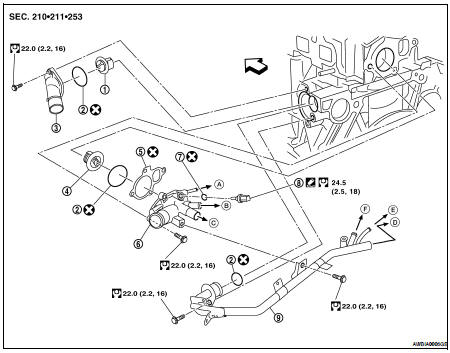
1. Thermostat
2. O-ring
3. Engine coolant inlet
4. Water control valve
5. Gasket
6. Engine coolant outlet
7. Copper washer
8. Engine coolant temperature sensor
9. Heater pipe
A. To electric throttle control
B. To oil cooler
C. To heater
D. To heater
E. To electric throttle control
F. To oil cooler

WARNING: Never remove the radiator cap when the engine is hot. Serious burns could occur from high pressure coolant escaping from the radiator.
REMOVAL
CAUTION: Perform when the engine cold.
1. Drain engine coolant from the radiator. Refer to CO-12, "Changing Engine Coolant".
2. Remove the engine room cover using power tool.
3. Remove the air cleaner and air duct assembly. Refer to EM-25, "Removal and Installation".
4. Remove the upper radiator hose, heater pipe, electric throttle control actuator inlet hose, and heater hose.
5. Remove the engine coolant outlet.
6. Remove the water control valve.
INSPECTION AFTER REMOVAL
• Place a thread so that it is caught in the valve of the water control valve. Immerse fully in a container filled with water. Heat while stirring.
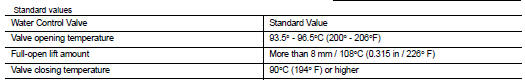
• The valve opening temperature is the temperature at which the valve opens and the falls from the thread.
• Continue heating. Check the full-open lift amount.
NOTE: The full-open lift amount standard temperature for the water control valve is the reference value.
• After checking the full-open lift amount, lower the water temperature and check the valve closing temperature.
INSTALLATION
Installation is in the reverse order of removal.
• Install the engine coolant temperature sensor.
Use Genuine RTV Silicone Sealant or equivalent. Refer to GI-15, "Recommended Chemical Products and Sealants".
• Install the water control valve with the whole circumference of the flange part fitting securely inside the rubber ring.
• Install the water control valve with the up-mark facing up and the frame center part facing upwards. The position deviation may be within the range of ±10°.
 Thermostat and thermostat housing
 Service data and specifications
(SDS)
Service data and specifications
(SDS)