Nissan Altima (L32) 2007-2012 Service Manual: Water outlet and water piping
Removal and Installation
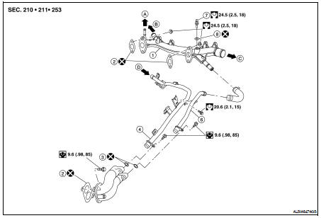
1. Water outlet
2. Gasket
3. O-ring
4. Heater pipe
5. Water connector
6. Water bypass pipe
7. Engine coolant temperature sensor
8. Washer
A. To electric throttle control actuator
B. To heater
C. To radiator
D. From heater or transmission oil cooler (if equipped)
WARNING: Never remove the radiator cap when the engine is hot. Serious burns could occur from high pressure coolant escaping from the radiator.
REMOVAL
CAUTION: Perform when the engine is cold.
1. Drain engine coolant from drain plugs on radiator and both sides of cylinder block. Refer to CO-35, "Changing Engine Coolant".
2. Remove engine cover using power tool.
3. Remove air duct and air cleaner case assembly. Refer to EM-129, "Removal and Installation".
4. Remove radiator upper hose and heater hose.
5. Remove connector(s) from heater pipe.
6. Disconnect engine coolant temperature sensor electrical connector on water outlet.
7. Remove water outlet, heater pipe, water connector, and water bypass pipe nuts and bolts.
INSTALLATION
1. Installation is in the reverse order of removal.
• Securely insert each hose, and install a clamp at a position where it does not interfere with the pipe bulge.
• When inserting heater pipe and water bypass pipe into water connector, apply neutral detergent to new O-rings.
CAUTION:
Use new O-rings for installation
• After installation refill engine coolant and check for leaks. Refer to CO-35, "Changing Engine Coolant" and CO-34, "System Inspection".
 Thermostat and thermostat housing
 Service data and specifications
(SDS)
Service data and specifications
(SDS)