Nissan Altima (L32) 2007-2012 Service Manual: Thermostat and thermostat housing
Removal and Installation
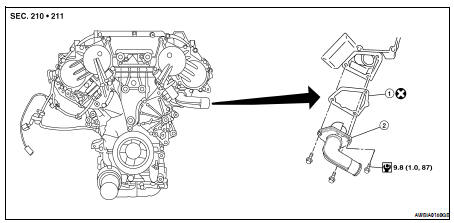
1. Gasket
2. Thermostat assembly
WARNING: Never remove the radiator cap when the engine is hot. Serious burns could occur from high pressure coolant escaping from the radiator.
REMOVAL
CAUTION: Perform when engine is cool.
1. Drain engine coolant from the radiator. Refer to CO-35, "Changing Engine Coolant".
2. Remove drive belts. Refer to EM-121, "Removal and Installation".
3. Remove water drain plug on water pump side of the engine. Refer to EM-206, "Disassembly and Assembly".
4. Disconnect lower radiator hose.
5. Remove engine coolant inlet and thermostat assembly.
• Do not disassemble engine coolant inlet and thermostat.
Replace them as a unit, if necessary.
INSPECTION AFTER REMOVAL
• Place a thread so that it is caught in the valves of the thermostat.
Immerse fully in a container filled with water. Heat while stirring.
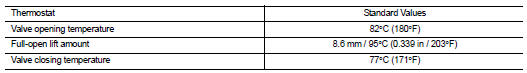
• The valve opening temperature is the temperature at which the valve opens and the falls from the thread.
• Continue heating. Check the full-open lift amount.
NOTE: The full-open lift amount standard temperature for the thermostat is the reference value.
• After checking the full-open lift amount, lower the water temperature and check the valve closing temperature.
INSTALLATION
Installation is in the reverse order of removal.
• Install thermostat with jiggle valve facing upward.
• After installation refill engine coolant and check for leaks. Refer to CO-35, "Changing Engine Coolant" and CO-34, "System Inspection".
CAUTION: Do not spill coolant in engine compartment. Use a shop cloth to absorb coolant.
 Water pump
 Water outlet and water piping