Nissan Altima (L32) 2007-2012 Service Manual: Air conditioner control
System Diagram
CONTROL SYSTEM
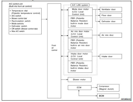
The control system consists of input sensors, switches, front air control and outputs. The relationship of these components is shown in the figure below:
System Description
CONTROL OPERATION
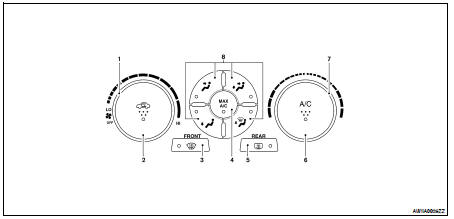
1. Blower control dial
2: Air recirculation switch
3: Defroster switch
4. MAX A/C ON/OFF switch
5: Rear defrost switch
6: A/C ON/OFF switch
7. Temperature control dial
8: Mode switches
Mode Switches
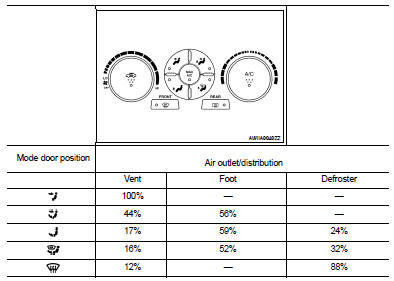
The air discharge outlets are controlled through the mode door.
Temperature Control Dial (Potentio Temperature Control) (LH) The set temperature is increased or decreased with this dial.
DEFROSTER (  ) Switch
Mode doors are set to the defrost position with this switch. Also, intake doors are set to the outside air position, and compressor turns ON.
A/C Switch
Compressor is ON or OFF with this switch.
(Pressing the A/C switch when the A/C switch is ON will turn OFF the A/C switch and compressor.)
Blower control dial/OFF switch
• The blower speed is manually controlled with this dial.
• Compressor and blower are OFF, intake doors and the mode doors are automatically controlled.
Recirculation (  ) Switch
• When REC (  ) switch is ON (REC
LED ON), air inlet is fixed to REC.
) switch is ON (REC
LED ON), air inlet is fixed to REC.
• When press intake switch again (REC LED OFF), air inlet is fixed to fresh air.
• When REC LED is turned ON, shifting mode position to D/F or DEF, or when
compressor is turned from ON
to OFF, the REC (  ) switch is
automatically turned OFF.
) switch is
automatically turned OFF.
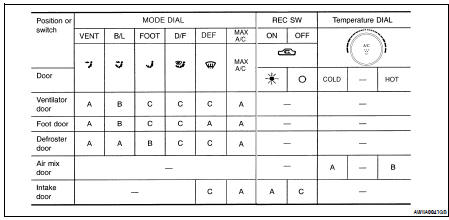
DISCHARGE AIR FLOW
SWITCHES AND THEIR CONTROL FUNCTION
AIR CONDITIONER LAN CONTROL SYSTEM
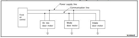
The LAN (Local Area Network) system consists of front air control, mode door motor, air mix door motor and intake door motor.
A configuration of these components is shown in the figure below.
SYSTEM CONSTRUCTION
A small network is constructed between the front air control, mode door motor, air mix door motor and intake door motor. The front air control and motors are connected by data transmission lines and motor power supply lines. The LAN network is built through the ground circuits of each door motors.
Addresses, motor opening angle signals, motor stop signals and error checking messages are all transmitted through the data transmission lines connecting the front air control and each door motor.
The following functions are contained in LCUs built into the mode door motor, the air mix door motor and the intake door motor.
• Address
• Motor opening angle signals
• Data transmission
• Motor stop and drive decision
• Opening angle sensor (PBR function)
• Comparison
• Decision (Front air control indicated value and motor opening angle comparison)
Operation
The front air control receives data from each of the sensors. The front air control sends mode door, air mix door and intake door opening angle data to the mode door motor LCU, air mix door motor LCUs and intake door motor LCU.
The mode door motor, air mix door motor and intake door motor read their respective signals according to the address signal. Opening angle indication signals received from the front air control and each of the motor position sensors is compared by the LCUs in each door motor with the existing decision and opening angles. Subsequently, HOT/COLD, DEF/VENT and FRE/REC operation is selected. The new selection data is returned to the front air control.
Transmission Data and Transmission Order
Front air control data is transmitted consecutively to each of the doors motor following the form shown in figure below.
START: • Initial compulsory signal is sent to each of the door motors.
ADDRESS: • Data sent from the front air control are selected according to data-based decisions made by the mode door motor, air mix door motors and intake door motor.
• If the addresses are identical, the opening angle data and error check signals are received by the door motor LCUs. The LCUs then make the appropriate error decision. If the opening angle data have no error, door control begins.
• If an error exists, the received data are rejected and corrected data received. Finally, door control is based upon the corrected opening angle data.
OPENING ANGLE: • Data that shows the indicated door opening angle of each door motor.
ERROR CHECK: • In this procedure, transmitted and received data is checked for errors. Error data are then compiled. The error check prevents corrupted data from being used by the mode door motor, the air mix door motor and the intake door motor. Error data can be related to the following symptoms.
- Malfunction of electrical frequency
- Poor electrical connections
- Signal leakage from transmission lines
- Signal level fluctuation
STOP SIGNAL:
• At the end of each transmission, a stop operation, in-operation, or internal malfunction message is delivered to the front air control. This completes one data transmission and control cycle.
AIR MIX DOOR CONTROL
The air mix door is controlled by the front air control based on input from the temperature dial setting--
A/C SWITCH
The air conditioner switch controls the A/C system. When the switch is pressed with the fan ON, the compressor will turn ON. The indicator will also illuminate.
TEMPERATURE CONTROL DIAL
Increases or decreases the set temperature.
BLOWER CONTROL DIAL
Manually controls the blower speed.
In the off position, the compressor and blower are OFF, the intake door is set to the outside air position.
RECIRCULATION (  ) SWITCH
OFF position: Outside air is drawn into the passenger compartment.
ON position: Interior air is recirculated inside the vehicle.
DEFROSTER SWITCH
Position the air mode doors to the defrost position. Also positions the intake doors to the outside air position.
The compressor remains ON until the ignition is turned OFF.
MODE SWITCHES
Controls the air discharge through control of mode door, also controls MAX A/C function.
REAR WINDOW DEFOGGER SWITCH
This switch turns the rear window defogger ON and OFF.
MAGNET CLUTCH CONTROL
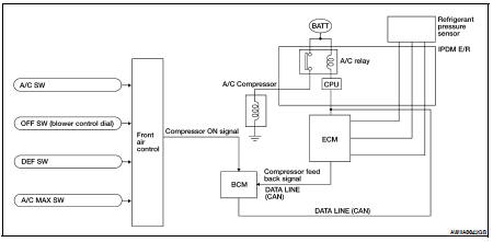
When A/C switch is pressed, or the defroster mode switch is pressed, the front air control outputs a compressor ON signal to the BCM.
The BCM then sends a compressor ON signal to the ECM, via CAN communication line. The ECM judges whether compressor can be turned ON, based on each sensor status (refrigerant-pressure sensor signal, throttle angle, etc.). If it judges compressor can be turned ON, it sends compressor ON signal to IPDM E/R, via CAN communication.
Upon receipt of compressor ON signal from ECM, IPDM E/R turns A/C relay ON to operate compressor.
Component Part Location
ENGINE COMPARTMENT
Refer to HAC-104, "Component Part Location".
PASSENGER COMPARTMENT
Refer to HAC-104, "Component Part Location".
Component Description
Refer to HAC-106, "Component’s Role".
 Function information
 Diagnosis system (ECM)