Nissan Altima (L32) 2007-2012 Service Manual: ASCD Indicator
Description
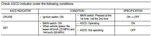
The ASCD operation status is indicated by two indicators, (CRUISE and SET on
the information display) on
the combination meter.
CRUISE indicator is displayed to indicate that ASCD system is ready for
operation when MAIN switch on
ASCD steering switch is turned ON.
SET indicator is displayed when the following conditions are met.
• CRUISE indicator is displayed.
• SET/COAST switch on ASCD steering switch is turned ON while vehicle speed is
within the range of ASCD
setting.
SET indicator is displayed during ASCD control.
Refer to EC-603, "System Description" for the ASCD function.
Component Function Check
1.ASCD INDICATOR FUNCTION
Is the inspection result normal?
YES >> INSPECTION END
NO >> Go to EC-948, "Diagnosis Procedure".
Diagnosis Procedure
1.CHECK DTC
Check that DTC UXXXX is not displayed.
Is the inspection result normal?
YES >> GO TO 2.
NO >> Perform trouble diagnosis for DTC UXXXX.
2.CHECK COMBINATION METER OPERATION
Refer to MWI-38, "CONSULT-III Function (METER/M&A)".
Is the inspection result normal?
YES >> GO TO 3.
NO >> Check combination meter circuit. Refer to MWI-5, "METER SYSTEM : System
Diagram".
3.CHECK INTERMITTENT INCIDENT
Refer to GI-42, "Intermittent Incident".
>> INSPECTION END
Description
When the brake pedal is depressed, ASCD brake switch is turned OFF and stop
lamp switch is turned ON.
ECM detects the state of the brake pedal by this input of two kinds (ON/OFF
s ...
Description
The ECM controls the cooling fan corresponding to the vehicle speed, engine
colant temperature, refrigerant
pressure, and air conditioner ON signal. The control system has 4-step cont ...
Other materials: Warning/Indicator lights (other)
For additional information on warnings
and indicators, see "Vehicle information
display-5 inch (13 cm) Type A" or
"Vehicle information display 7 inch (18 cm)
Type B".
Automatic brake hold
indicator light (white/green)
(if so equipped)
The automatic brake hold indicator light
(white) illuminates whe ...
Seat belt warning light and chime
The driver and front passenger seat is
equipped with an enhanced seat belt reminder
function.
A visual and audible alert will operate at
speeds of approximately 9 mph (15 km/h)
or more under the following conditions:
If the driver seat belt is not fastened.
The front passenger’s seat belt is ...
Booster seats
For additional information on installing a
booster seat in your vehicle, follow the instructions
outlined in this section.
Precautions on booster seats
WARNING
If a booster seat and seat belt are not
used properly, the risk of a child being
injured or killed in a sudden stop or collision
greatly inc ...
 ASCD Brake switch
 Cooling fan