Nissan Altima (L32) 2007-2012 Service Manual: B2109 steering lock relay
Description
The steering lock relay ON signal is transmitted to IPDM E/R by BCM via CAN
communication.
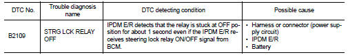
IPDM E/R turns the steering lock relay ON and transmits the release of the
steering to BCM.
DTC Logic
DTC DETECTION LOGIC
NOTE:
• If DTC B2109 is displayed with DTC U1000, first perform the trouble diagnosis
for DTC U1000. Refer to
SEC-235, "DTC Logic".
• If DTC B2109 is displayed with DTC U1010, first perform the trouble diagnosis
for DTC U1010. Refer to
SEC-236, "DTC Logic".
DTC CONFIRMATION PROCEDURE
1.PERFORM DTC CONFIRMATION PROCEDURE
1. Press the push-button ignition switch under the following conditions and
wait for at least 1 second.
- CVT selector lever is in the P or N position
- Do not depress the brake pedal
2. Check “Self diagnostic result” with CONSULT-III.
Is DTC detected?
YES >> Refer to SEC-242, "Diagnosis Procedure".
NO >> Inspection End.
Diagnosis Procedure
1.CHECK POWER SUPPLY CIRCUIT
Check IPDM E/R power supply circuit. Refer to PCS-23, "Diagnosis Procedure".
Is the inspection result normal?
YES >> GO TO 2
NO >> Repair the malfunctioning parts
2.CHECK FUSE
1. Turn ignition switch OFF.
2. Check 10A fuse (No. 40, located in IPDM E/R).
Is the inspection result normal?
YES >> Replace IPDM E/R. Refer to PCS-48, "Removal and Installation".
NO >> Check the following.
• Harness for open or short between IPDM E/R and battery
• Fuse
Description
The steering lock relay ON signal is transmitted to IPDM E/R by BCM via CAN
communication.
IPDM E/R turns the steering lock relay ON and transmits the release of the
steering to B ...
Description
There are 2 switches in the electronic steering column lock. IPDM E/R
compares those 2 switches conditions
to judge the present steering status and transmit the result to BCM via CAN ...
Other materials: Vehicle information display - 5 inch (13 cm) Type A (if so equipped)
The vehicle information display is located
to the left of the speedometer. It displays
such items as:
Vehicle settings
Indicators and warnings
Information/warning messages
Tire pressure information
Drive computer information
Cruise control system information
Driving Aids (if so equipped)
N ...
Folding rear seat
Interior trunk access
The trunk can be accessed from the driver
side and passenger side of the rear seat for
loading and unloading, as shown.
1. Move the front passenger seat to the
most forward position.
2. Open the access cover on the rear parcel
shelf.
3. Insert a key or another suitable tool
...
LATCH (Lower Anchors and Tethers for
CHildren) system
LATCH system anchor locations
Your vehicle is equipped with special anchor
points that are used with LATCH system
compatible child restraints. This system
may also be referred to as the ISOFIX
or ISOFIX compatible system. With this system,
you do not have to use a vehicle seat
belt to secure the ch ...
 B2108 steering lock relay
 B210a steering lock condition switch