Nissan Altima (L32) 2007-2012 Service Manual: B2556 push-button ignition switch
Description
The switch that changes the power supply position. BCM maintains the power supply position status. BCM changes the power supply position with the operation of the push-button ignition switch.
DTC Logic
DTC DETECTION LOGIC
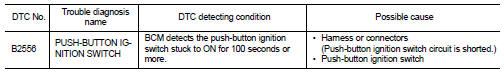
DTC CONFIRMATION PROCEDURE
1.PERFORM DTC CONFIRMATION PROCEDURE
1. Start the engine and wait for at least 100 seconds.
2. Check “Self Diagnostic Result” with CONSULT-III.
Is DTC detected? YES >> Refer to SEC-271, "Diagnosis Procedure".
NO >> Inspection End.
Diagnosis Procedure
1.CHECK PUSH-BUTTON IGNITION SWITCH INPUT SIGNAL
1. Turn ignition switch OFF.
2. Disconnect push-button ignition switch harness connector.
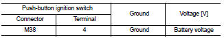
3. Check voltage between push-button ignition switch harness connector and ground.
Is the inspection result normal? YES >> GO TO 2
NO >> GO TO 4
2.CHECK PUSH-BUTTON IGNITION SWITCH
Refer to SEC-272, "Component Inspection".
Is the inspection result normal? YES >> GO TO 3
NO >> Replace push-button ignition switch. Refer to SEC-410, "Removal and Installation".
3.CHECK INTERMITTENT INCIDENT
Refer to GI-42, "Intermittent Incident".
>> Inspection End.
4.CHECK PUSH-BUTTON IGNITION SWITCH CIRCUIT FOR SHORT
1. Disconnect BCM harness connector and IPDM E/R harness connector.
2. Check continuity between push-button ignition switch harness connector and ground.
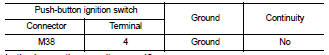
Is the inspection result normal? YES >> Replace BCM. Refer to BCS-96, "Removal and Installation".
NO >> Repair harness or connector.
Component Inspection
1.CHECK PUSH-BUTTON IGNITION SWITCH
1. Turn ignition switch OFF.
2. Disconnect push-button ignition switch harness connector.
3. Check continuity between push-button ignition switch terminals under the following conditions.
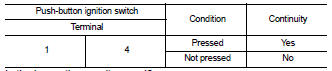
Is the inspection result normal? YES >> Inspection End.
NO >> Replace push-button ignition switch. Refer to SEC-410, "Removal and Installation".
 B2555 stop lamp
 B2557 vehicle speed