Nissan Altima (L32) 2007-2012 Service Manual: B2603 shift position status
Description
BCM confirms the shift position with the following 2 signals.
• CVT selector lever
• P/N position switch
DTC Logic
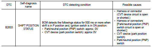
DTC DETECTION LOGIC
NOTE: • If DTC B2603 is displayed with DTC U1000, first perform the trouble diagnosis for DTC U1000. Refer to SEC-36, "DTC Logic".
• If DTC B2603 is displayed with DTC U1010, first perform the trouble diagnosis for DTC U1010. Refer to SEC-37, "DTC Logic".
DTC CONFIRMATION PROCEDURE
1.PERFORM DTC CONFIRMATION PROCEDURE
1. Start the engine under the following conditions and wait for at least 1 second.
- CVT selector lever is in the P position.
- Do not depress the brake pedal.
2. Shift to N and wait for at least 1 second.
3. Shift to any gear other than P or N and wait for at least 1 second.
4. Check “Self diagnostic result” with CONSULT-III.
Is DTC detected? YES >> Refer to SEC-81, "Diagnosis Procedure".
NO >> Inspection End.
Diagnosis Procedure
1.CHECK DTC WITH IPDM E/R
Check “Self diagnostic result” with CONSULT-III. Refer to PCS-45, "DTC Index".
Is the inspection result normal? YES >> GO TO 2
NO >> Repair or replace malfunctioning parts.
2.CHECK PNP SWITCH CIRCUIT
1. Turn ignition switch OFF.
2. Disconnect TCM harness connector and BCM harness connector.
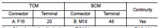
3. Check continuity between TCM harness connector F16 (A) terminal 20 and BCM harness connector M18 (B) terminal 48.
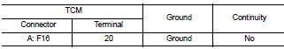
4. Check continuity between TCM harness connector F16 (A) terminal 20 and ground.
Is the inspection result normal? YES >> GO TO 3
NO >> Repair harness or connector.
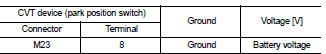
3.CHECK CVT DEVICE POWER SUPPLY
1. Turn ignition switch OFF.
2. Disconnect CVT device (park position switch) harness connector.
3. Check voltage between CVT device (park position switch) harness connector and ground.
Is the inspection result normal? YES >> GO TO 5
NO >> GO TO 4
4.CHECK CVT DEVICE POWER SUPPLY CIRCUIT
1. Disconnect BCM harness connector.
2. Check continuity between BCM harness connector M19 (A) terminal 84 and CVT device (park position switch) harness connector M23 (B) terminal 8.
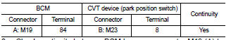
3. Check continuity between BCM harness connector M19 (A) terminal 84 and ground.
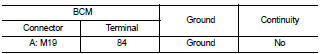
Is the inspection result normal? YES >> Replace BCM. Refer to BCS-96, "Removal and Installation".
NO >> Repair harness or connector.
5.CHECK CVT DEVICE CIRCUIT
1. Disconnect BCM harness connector.
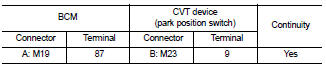
2. Check continuity between BCM harness connector M19 (A) terminal 87 and CVT device (park position switch) harness connector M23 (B) terminal 9.
3. Check continuity between BCM harness connector M19 (A) terminal 87 and ground.
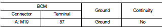
Is the inspection result normal? YES >> GO TO 6
NO >> Repair harness or connector.
6.CHECK CVT DEVICE
Refer to SEC-78, "Component Inspection".
Is the inspection result normal? YES >> GO TO 7
NO >> Replace CVT device. Refer to TM-255, "Removal and Installation" (RE0F09B) or TM-431, "Removal and Installation" (RE0F10A).
7.CHECK INTERMITTENT INCIDENT
Refer to GI-42, "Intermittent Incident".
>> Inspection End.
 B2602 shift position
 B2604 PNP switch