Nissan Altima (L32) 2007-2012 Service Manual: B260D steering lock unit
Description
The electronic steering column lock performs the check by itself according to
the steering lock status (before
lock, after lock and unlock).
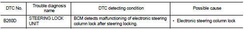
DTC Logic
DTC DETECTION LOGIC
DTC CONFIRMATION PROCEDURE
1.PERFORM DTC CONFIRMATION PROCEDURE
1. Turn ignition switch ON.
2. Turn ignition switch OFF.
3. Press door switch.
4. Check “Self diagnostic result” with CONSULT-III.
Is DTC detected?
YES >> Refer to SEC-490, "Diagnosis Procedure".
NO >> Inspection End.
Diagnosis Procedure
1.INSPECTION START
1. Turn ignition switch ON.
2. Check “Self diagnostic result” with CONSULT-III.
3. Touch “ERASE”.
4. Perform DTC Confirmation Procedure.
See SEC-490, "DTC Logic".
Is the DTC B260D displayed again?
YES >> Replace electronic steering column lock.
NO >> Inspection End.
Description
The electronic steering column lock performs the check by itself according to
the steering status.
DTC Logic
DTC DETECTION LOGIC
DTC CONFIRMATION PROCEDURE
1.PERFORM DTC CONFIRM ...
Description
BCM receives the engine status signal from ECM via CAN communication.
DTC Logic
DTC DETECTION LOGIC
NOTE:
• If DTC B260F is displayed with DTC U1000, first perform the trouble diag ...
Other materials: Child safety
WARNING
Do not allow children to play with the
seat belts. Most seating positions are
equipped with Automatic Locking Retractor
(ALR) mode seat belts. If the seat
belt becomes wrapped around a child’s
neck with the ALR mode activated, the
child can be seriously injured or killed if
the seat belt r ...
Trip computer
1. Vehicle speed
The vehicle speed mode shows the current
vehicle speed and the average vehicle
speed since the last reset.
Average vehicle speed:
Press the OK button on the steering wheel
to bring up the drive computer Reset
menu, and follow the instructions to reset.
For additional information, ...
Opener operation
Instrument panel
WARNING
Do not drive with the trunk lid open.
This could allow dangerous exhaust
gases to be drawn into the vehicle. For
additional information, see "Exhaust
gas (carbon monoxide)".
Intelligent Key
Closely supervise children when they
are around cars to prevent them
fro ...
 B260C steering lock unit
 B260F engine status