Nissan Altima (L32) 2007-2012 Service Manual: B2619 BCM
Description
BCM requests IPDM E/R to supply power to steering lock unit. After receiving
the power, the steering lock unit
transmits an ON signal to BCM.
DTC Logic
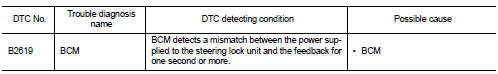
DTC DETECTION LOGIC
DTC CONFIRMATION PROCEDURE
1.PERFORM DTC CONFIRMATION PROCEDURE
1. Press the push-button ignition switch under the following conditions and
wait for at least 1 second.
- CVT selector lever is in the P position
- Do not depress brake pedal
2. Check “Self diagnostic result” with CONSULT-III.
Is DTC detected?
YES >> Refer to SEC-498, "Diagnosis Procedure".
NO >> Inspection End.
Diagnosis Procedure
1.INSPECTION START
1. Turn ignition switch ON.
2. Check “Self diagnostic result” with CONSULT-III.
3. Touch “ERASE”.
4. Perform DTC Confirmation Procedure.
See SEC-498, "DTC Logic".
Is the DTC B2619 displayed again?
YES >> Replace BCM. Refer to BCS-96, "Removal and Installation".
NO >> Inspection End.
Description
Located in IPDM E/R, it runs the starter motor. The starter relay is turned
ON by the BCM when the ignition
switch is in START position. IPDM E/R transmits the starter relay ON signal ...
Description
IPDM E/R transmits the push-button ignition switch status via CAN
communication to BCM. BCM receives
push-button ignition switch status by hardwire input. BCM compares the 2 signals
...
Other materials: Child safety
WARNING
Do not allow children to play with the
seat belts. Most seating positions are
equipped with Automatic Locking Retractor
(ALR) mode seat belts. If the seat
belt becomes wrapped around a child’s
neck with the ALR mode activated, the
child can be seriously injured or killed if
the seat belt r ...
How to use the vehicle information
display
The vehicle information display can be
changed using the ,
, and OK buttons located on the
steering
wheel.
- Use these buttons
to navigate the vehicle information
display.
OK - Change or select an item in the
vehicle information display.
- Returns to the previous
menu.
The OK, a ...
Warning lights, indicator lights and audible
reminders
Warning/Indicator light (red)
Brake warning light
Charge warning light
Electronic parking brake
indicator
light (if so equipped)
Engine oil pressure warning
light
Master warning light
Seat belt warning light and
chime
Security indicator light
Supplemental air bag warning
light
Warning/Indic ...
 B2617 starter relay circuit
 B261A push-button ignition switch