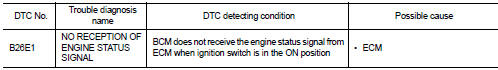
Nissan Altima (L32) 2007-2012 Service Manual: B26e1 no reception of engine status signal
Description
BCM receives the engine status signal from ECM via CAN communication.
DTC Logic
DTC DETECTION LOGIC
NOTE:
• If DTC B26E1 is displayed with DTC U1000, first perform the trouble diagnosis
for DTC U1000. Refer to
SEC-433, "DTC Logic".
• If DTC B26E1 is displayed with DTC U1010, first perform the trouble diagnosis
for DTC U1010. Refer to
SEC-434, "DTC Logic".
DTC CONFIRMATION PROCEDURE
1.PERFORM DTC CONFIRMATION PROCEDURE
1. Turn ignition switch ON under the following conditions.
- CVT selector lever is in the P or N position.
- Do not depress the brake pedal.
2. Check “Self diagnostic result” with CONSULT-III.
Is DTC detected?
YES >> Refer to SEC-501, "Diagnosis Procedure".
NO >> Inspection End.
Diagnosis Procedure
1.INSPECTION START
1. Turn ignition switch ON.
2. Check “Self diagnostic result” with CONSULT-III.
3. Touch “ERASE”.
4. Perform DTC Confirmation Procedure.
See SEC-501, "DTC Logic".
Is the DTC B26E1 displayed again?
YES >> GO TO 2
NO >> Inspection End.
2.REPLACE ECM
1. Replace ECM.
2. Refer to EC-560, "BASIC INSPECTION : Special Repair Requirement" (QR25DE
except California) or
EC-24, "BASIC INSPECTION : Special Repair Requirement" (QR25DE California).
>> Inspection End.
Description
IPDM E/R transmits the push-button ignition switch status via CAN
communication to BCM. BCM receives
push-button ignition switch status by hardwire input. BCM compares the 2 signals
...
BCM
Diagnosis Procedure
1. CHECK FUSE AND FUSIBLE LINK
Check if the following BCM fuse or fusible link are blown.
Is the fuse or fusible link blown?
YES >> Replace the blown fuse or fus ...
Other materials: Warning lights, indicator lights and audible
reminders
Warning/Indicator light (red)
Brake warning light
Charge warning light
Electronic parking brake
indicator
light (if so equipped)
Engine oil pressure warning
light
Master warning light
Seat belt warning light and
chime
Security indicator light
Supplemental air bag warning
light
Warning/Indic ...
Heated seat switches (if so equipped)
WARNING
Do not use or allow occupants to use
the seat heater if you or the occupants
cannot monitor elevated seat temperatures
or have an inability to feel
pain in body parts that contact the
seat. Use of the seat heater by such
people could result in serious injury.
CAUTION
The battery could run ...
Seat belt extenders
If, because of body size or driving position, it
is not possible to properly fit the lap/
shoulder belt and fasten it, an extender
that is compatible with the installed seat
belts is available for purchase. The extender
adds approximately 8 in (200 mm)
of length and may be used for either the
driver ...
 B261A push-button ignition switch
 Power supply and ground circuit