Nissan Altima (L32) 2007-2012 Service Manual: B Terminal circuit
Description
The terminal “1” (B) circuit supplies power to charge the battery and operate
the vehicles electrical system.
Diagnosis Procedure
1.CHECK TERMINAL “1” CONNECTION
1. Turn ignition switch OFF.
2. Check if terminal “1” is clean and tight.
Is the inspection result normal?
YES >> GO TO 2
NO >> Repair terminal “1” connection. Confirm repair by performing complete
Starting/Charging system
test. Refer to Technical Service Bulletin.
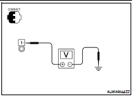
2.CHECK TERMINAL “1” CIRCUIT
Check voltage between generator connector F6 terminal 1 and
ground.
Is the inspection result normal?
YES >> GO TO 3
NO >> Check harness for open between generator and fusible
link.
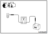
3.CHECK TERMINAL “1” CONNECTION (VOLTAGE DROP TEST)
1. Start engine, then engine running at idle and warm.
2. Check voltage between battery positive terminal and generator
connector F6 terminal 1.
Is the inspection result normal?
YES >> Terminal “1” circuit is normal. Refer to CHG-2, "Work
Flow".
NO >> Check harness between battery and generator for high
resistance.
Inspection Procedure
CAUTION:
When performing this inspection, always use a charged battery that has completed
the battery inspection.
(When the charging rate of the battery is low, the respons ...
Description
The terminal “2” (L) circuit controls the charge warning lamp. The charge
warning lamp illuminates when the
ignition switch is set to ON or START. When the generator is providing
...
Other materials: Programming HomeLink for Canadian
customers and gate openers
Canadian radio-frequency laws require
transmitter signals to "time-out" (or quit)
after several seconds of transmission -
which may not be long enough for
HomeLink to pick up the signal during
training. Similar to this Canadian law, some
U.S. gate operators are designed to "timeout"
in the same mann ...
System temporarily unavailable
For vehicles with the 7 inch (18 cm) display
When radar blockage is detected, the system
will be deactivated automatically. The
"Unavailable: Side Radar Obstruction"
warning message will appear in the vehicle
information display.
The systems are not available until the
conditions no longer exist.
...
Settings
The setting mode allows you to change the
information displayed in the vehicle information
display. It also allows you to change
vehicle functions:
VDC
Driver Assistance
Clock
Meter Settings
Vehicle Settings
Maintenance
Alarm
Tire Pressures
Unit
Language
Factory Reset
VDC
The VDC Settin ...


 Power generation voltage variable
control system operation inspection
 L Terminal circuit