Nissan Altima (L32) 2007-2012 Service Manual: Power generation voltage variable control system operation inspection
Inspection Procedure
CAUTION: When performing this inspection, always use a charged battery that has completed the battery inspection.
(When the charging rate of the battery is low, the response speed of the voltage change will become slow. This can cause an incorrect inspection.)
1.CHECK ECM (CONSULT-III)
Perform ECM self-diagnosis with CONSULT-III. Refer to EC-125, "CONSULT-III Function" (QR25DE for California), EC-654, "CONSULT-III Function" (QR25DE except for California) or EC-1155, "CONSULT-III Function" (VQ35DE).
Self-diagnostic results content
No malfunction detected>> GO TO 2
Malfunction detected>> Check applicable parts, and repair or replace corresponding parts.
2.CHECK OPERATION OF POWER GENERATION VOLTAGE VARIABLE CONTROL SYSTEM
1. Connect CONSULT-III and start the engine.
2. The selector lever is in “P” or “N” position and all of the electric loads and A/C, etc. are turned OFF.
3. Select “ALTERNATOR DUTY” in “Active Test” of “ENGINE”, and then check the value of “BATTERY VOLT” monitor when DUTY value of “ALTERNATOR DUTY” is set to 40.0 %.
4. Check the value of “BATTERY VOLT” monitor when DUTY value of “ALTERNATOR DUTY” is set to 80.0%.
Is the measurement value within the specification? YES >> Inspection End.
NO >> GO TO 3
3.CHECK IPDM E/R (CONSULT-III)
Perform IPDM E/R self-diagnosis with CONSULT-III. Refer to PCS-17, "CONSULT - III Function (IPDM E/R)".
Self-diagnostic results content
No malfunction detected>> GO TO 4
Malfunction detected>> Check applicable parts, and repair or replace corresponding parts.
4.CHECK HARNESS BETWEEN GENERATOR AND IPDM E/R
1. Turn ignition switch OFF.
2. Disconnect generator connector and IPDM E/R connector.
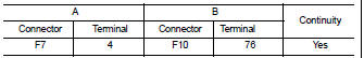
3. Check continuity between generator harness connector F7 (A) terminal 4 and IPDM E/R harness connector F10 (B) terminal 76.
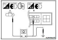
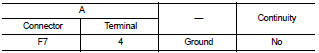
4. Check continuity between generator harness connector F7 (A) terminal 4 and ground.
Is the inspection result normal? YES >> Replace IPDM E/R. Refer to PCS-48, "Removal and Installation".
NO >> Repair harness or connector between IPDM E/R and generator.
 Charging system preliminary inspection
 B Terminal circuit